HP ML150 HP ProLiant ML150 G6 Server Maintenance and Service Guide - Page 62
Slightly lift up the power supply and then push toward the front of the chassis until it clears
 |
UPC - 884420743644
View all HP ML150 manuals
Add to My Manuals
Save this manual to your list of manuals |
Page 62 highlights
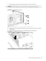
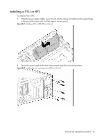
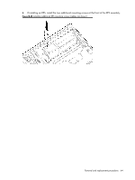
7. Remove the eight mounting screws that secure the PSU to the rear chassis panel. WARNING: The PSU is heavy and can cause personal injury or damage system components. Figure 3-39 Removing the PSU mounting screws 8. Slightly lift up the power supply and then push toward the front of the chassis until it clears the support ledge. 9. Tilt the power supply toward processor 1 and carefully remove it from the chassis. Figure 3-40 Removing the PSU (cables not shown) Removal and replacement procedures 62
-
 1
1 -
2
-
3
-
4
-
5
-
6
-
7
-
8
-
9
-
10
-
11
-
12
-
13
-
14
-
15
-
16
-
17
-
18
-
19
-
20
-
21
-
22
-
23
-
24
-
25
-
26
-
27
-
28
-
29
-
30
-
31
-
32
-
33
-
34
-
35
-
36
-
37
-
38
-
39
-
40
-
41
-
42
-
43
-
44
-
45
-
46
-
47
-
48
-
49
-
50
-
51
-
52
-
53
-
54
-
55
-
56
-
 57
57 -
 58
58 -
 59
59 -
 60
60 -
 61
61 -
 62
62 -
 63
63 -
 64
64 -
 65
65 -
 66
66 -
 67
67 -
68
-
69
-
70
-
71
-
72
-
73
-
74
-
75
-
76
-
77
-
78
-
79
-
80
-
81
-
82
-
83
-
84
-
85
-
86
-
87
-
88
-
89
-
90
-
91
-
92
-
93
-
94
-
95
-
96
-
97
-
98
-
99
-
100
-
101
-
102
-
103
-
104
-
105
-
106
 |
 |
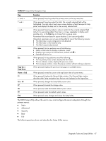
7.
Remove the eight mounting screws that secure the PSU to the rear chassis panel.
WARNING:
The PSU is heavy and can cause personal injury or damage system components.
Figure
3
-39
Removing the PSU mounting screws
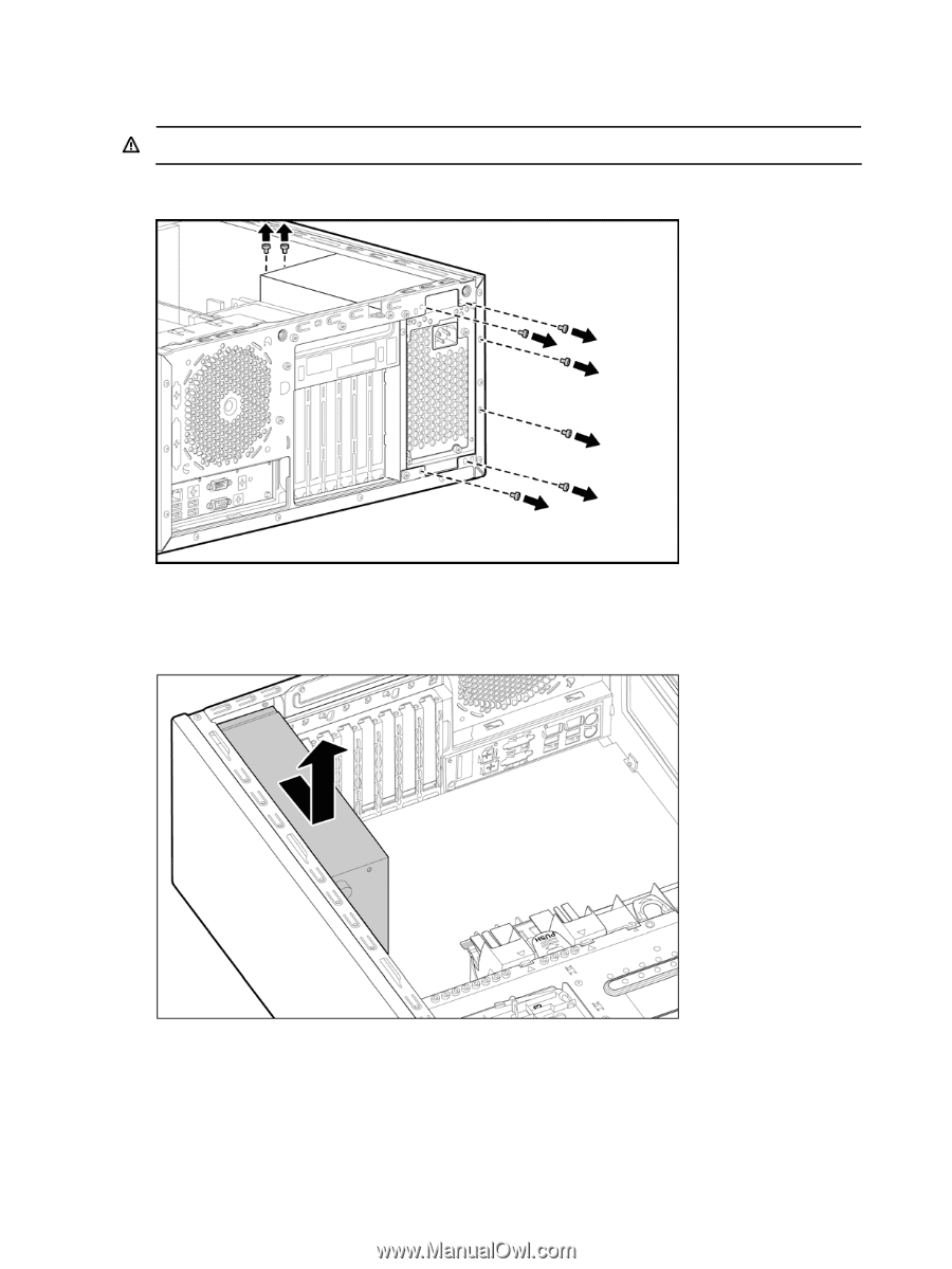
8.
Slightly lift up the power supply and then push toward the front of the chassis until it clears the
support ledge.
9.
Tilt the power supply toward processor 1 and carefully remove it from the chassis.
Figure
3
-40
Removing the PSU (cables not shown)
Removal and replacement procedures
62