HP ML150 HP ProLiant ML150 G6 Server Maintenance and Service Guide - Page 88
Components, Switches, and Indicators, Front and Rear Panel Components, Switches, and Indicators - g6 q
 |
UPC - 884420743644
View all HP ML150 manuals
Add to My Manuals
Save this manual to your list of manuals |
Page 88 highlights
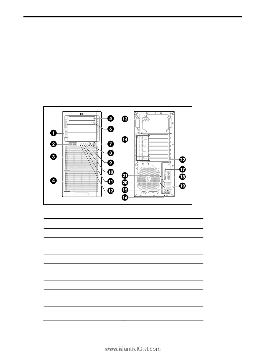
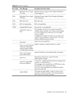
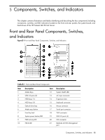
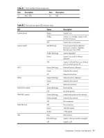
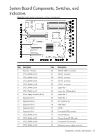
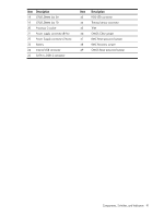
5 Components, Switches, and Indicators This chapter contains illustrations and tables identifying and describing the key components (including connectors), switches, and LED indicators located on the front and rear panels, the system board, and hard drives of the HP ProLiant ML150 G6 Server. Front and Rear Panel Components, Switches, and Indicators Figure 5-1 Front and Rear Panel Components, Switches, and Indicators Table 5-1 Front and Rear Panel Components Item 1 2 3 4 5 6 7 8 9 10 Description Media bays USB 2.0 ports (2) HDD bays 1-4 HDD bays 5-8 Optical drive bay Media eject button Front key lock System power button/LED HDD activity LED NIC2 LED Item 12 13 14 15 16 17 18 19 20 21 Description System Health LED AC input connector Expansion slots Keyboard connector Mouse connector Serial port connector VGA connector USB 2.0 ports (4) NIC connector Dedicate LO100 Management port Components, Switches, and Indicators 88
-
 1
1 -
2
-
3
-
4
-
5
-
6
-
7
-
8
-
9
-
10
-
11
-
12
-
13
-
14
-
15
-
16
-
17
-
18
-
19
-
20
-
21
-
22
-
23
-
24
-
25
-
26
-
27
-
28
-
29
-
30
-
31
-
32
-
33
-
34
-
35
-
36
-
37
-
38
-
39
-
40
-
41
-
42
-
43
-
44
-
45
-
46
-
47
-
48
-
49
-
50
-
51
-
52
-
53
-
54
-
55
-
56
-
57
-
58
-
59
-
60
-
61
-
62
-
63
-
64
-
65
-
66
-
67
-
68
-
69
-
70
-
71
-
72
-
73
-
74
-
75
-
76
-
77
-
78
-
79
-
80
-
81
-
82
-
 83
83 -
 84
84 -
 85
85 -
 86
86 -
 87
87 -
 88
88 -
 89
89 -
 90
90 -
 91
91 -
 92
92 -
 93
93 -
94
-
95
-
96
-
97
-
98
-
99
-
100
-
101
-
102
-
103
-
104
-
105
-
106
 |
 |