HP ML150 HP ProLiant ML150 G6 Server Maintenance and Service Guide - Page 59
System board removal and replacement procedure, Removing the system board
 |
UPC - 884420743644
View all HP ML150 manuals
Add to My Manuals
Save this manual to your list of manuals |
Page 59 highlights
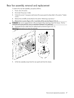
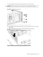
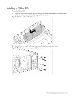
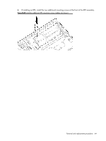
System board removal and replacement procedure Removing the system board To remove the system board, proceed as follows: 1. Power down the server. 2. Disconnect the power cord(s). 3. Unlock the server if necessary and remove the access panel as described in the section "System covers." 4. Place the server on its side with the open side up. 5. Remove all expansion cards as described in the section "Removing an expansion card." 6. Remove the system fans as described in the section "System fans." 7. Remove the processor heatsink(s) as described in the section "Removing a processor." NOTE: If the system board is to be reused, only the processor heatsink needs to be removed for this procedure. The processor(s) can be left in the socket(s). 8. Disconnect all power supply cables from the system board. 9. Disconnect all mass storage device data cables from the system board. 10. Locate the 11 mounting screws from the system board (indicated by arrows in the following figure). Figure 3-38 System board mounting screw locations 11. Loosen and remove the mounting screws from the system board. 12. Grasping the system board by the edges, lift the front edge of the system board up slightly, pull the board away from the rear panel and lift up from the chassis. 13. Place the board on a grounded mat or in a protective anti-static bag. End of procedure. Removal and replacement procedures 59
-
 1
1 -
2
-
3
-
4
-
5
-
6
-
7
-
8
-
9
-
10
-
11
-
12
-
13
-
14
-
15
-
16
-
17
-
18
-
19
-
20
-
21
-
22
-
23
-
24
-
25
-
26
-
27
-
28
-
29
-
30
-
31
-
32
-
33
-
34
-
35
-
36
-
37
-
38
-
39
-
40
-
41
-
42
-
43
-
44
-
45
-
46
-
47
-
48
-
49
-
50
-
51
-
52
-
53
-
 54
54 -
 55
55 -
 56
56 -
 57
57 -
 58
58 -
 59
59 -
 60
60 -
 61
61 -
 62
62 -
 63
63 -
 64
64 -
65
-
66
-
67
-
68
-
69
-
70
-
71
-
72
-
73
-
74
-
75
-
76
-
77
-
78
-
79
-
80
-
81
-
82
-
83
-
84
-
85
-
86
-
87
-
88
-
89
-
90
-
91
-
92
-
93
-
94
-
95
-
96
-
97
-
98
-
99
-
100
-
101
-
102
-
103
-
104
-
105
-
106
 |
 |
