HP ML150 HP ProLiant ML150 G6 Server Maintenance and Service Guide - Page 56
Return the server to the upright position., Connect the power cables to the power supplies.
 |
UPC - 884420743644
View all HP ML150 manuals
Add to My Manuals
Save this manual to your list of manuals |
Page 56 highlights
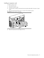
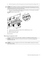
To replace the front fan holder assembly, 1. Connect the system fan cable to system board connector (Figure 3-34,1) 2. Installing system fan to chassis. (Figure 3-34,2) Figure 3-34 Replace the front fan/ PCI card holder assembly Figure 3-35 Installing the system fan 3. Reinstall the air baffle. 4. Reinstall the access panel and tighten the thumbscrews. 5. Return the server to the upright position. 6. Connect the power cables to the power supplies. End of procedure. Removal and replacement procedures 56
-
 1
1 -
2
-
3
-
4
-
5
-
6
-
7
-
8
-
9
-
10
-
11
-
12
-
13
-
14
-
15
-
16
-
17
-
18
-
19
-
20
-
21
-
22
-
23
-
24
-
25
-
26
-
27
-
28
-
29
-
30
-
31
-
32
-
33
-
34
-
35
-
36
-
37
-
38
-
39
-
40
-
41
-
42
-
43
-
44
-
45
-
46
-
47
-
48
-
49
-
50
-
 51
51 -
 52
52 -
 53
53 -
 54
54 -
 55
55 -
 56
56 -
 57
57 -
 58
58 -
 59
59 -
 60
60 -
 61
61 -
62
-
63
-
64
-
65
-
66
-
67
-
68
-
69
-
70
-
71
-
72
-
73
-
74
-
75
-
76
-
77
-
78
-
79
-
80
-
81
-
82
-
83
-
84
-
85
-
86
-
87
-
88
-
89
-
90
-
91
-
92
-
93
-
94
-
95
-
96
-
97
-
98
-
99
-
100
-
101
-
102
-
103
-
104
-
105
-
106
 |
 |

To replace the front fan holder assembly,
1.
Connect the system fan cable to system board connector (Figure 3-34,1)
2.
Installing system fan to chassis. (Figure 3-34,2)
Figure 3-34
Replace the front fan/ PCI card holder assembly
Figure 3-35
Installing the system fan
3.
Reinstall the air baffle.
4.
Reinstall the access panel and tighten the thumbscrews.
5.
Return the server to the upright position.
6.
Connect the power cables to the power supplies.
End of procedure.
Removal and replacement procedures
56