HP ML150 HP ProLiant ML150 G6 Server Maintenance and Service Guide - Page 48
Table, CAUTION
 |
UPC - 884420743644
View all HP ML150 manuals
Add to My Manuals
Save this manual to your list of manuals |
Page 48 highlights
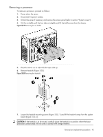
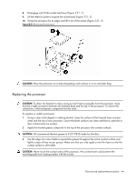
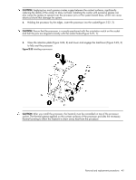
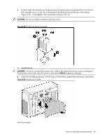
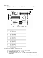
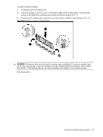
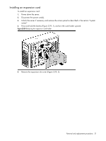
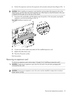
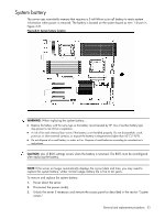
• Supported technologies: 1GB, 2GB, 4GB x12 devices for registered and 1GB, 2GB x 12 devices for un-buffered. • For best performance, DIMMs should be installed in symmetrical (balance-capacity) pairs. Table 3-2 DIMM's slot Configurations 1D 2A 3E 4B 5F 6C - • - - - - - • - • - - - • - • - • • • - • - • • • • • - • • • • • • • - : Empty •: DIMM installed To remove a memory module: 1. Power down the server. 2. Disconnect the power cord(s). 3. Unlock the server if necessary and remove the access panel as described in the section "System covers." 4. Remove the air baffle by pulling up slightly on the four tabs and lifting the baffle away from the chassis. 5. Remove the hard drive fan holder if needed. 6. Completely open the holding clips securing the module (Figure 3-26, 1). 7. Gently pull the memory module upward to remove it from the slot (Figure 3-26, 2). Figure 3-26 Removing a memory module (DIMM) CAUTION: Place the memory module on a static-dissipating work surface or inside an anti-static bag. Removal and replacement procedures 48
-
 1
1 -
2
-
3
-
4
-
5
-
6
-
7
-
8
-
9
-
10
-
11
-
12
-
13
-
14
-
15
-
16
-
17
-
18
-
19
-
20
-
21
-
22
-
23
-
24
-
25
-
26
-
27
-
28
-
29
-
30
-
31
-
32
-
33
-
34
-
35
-
36
-
37
-
38
-
39
-
40
-
41
-
42
-
 43
43 -
 44
44 -
 45
45 -
 46
46 -
 47
47 -
 48
48 -
 49
49 -
 50
50 -
 51
51 -
 52
52 -
 53
53 -
54
-
55
-
56
-
57
-
58
-
59
-
60
-
61
-
62
-
63
-
64
-
65
-
66
-
67
-
68
-
69
-
70
-
71
-
72
-
73
-
74
-
75
-
76
-
77
-
78
-
79
-
80
-
81
-
82
-
83
-
84
-
85
-
86
-
87
-
88
-
89
-
90
-
91
-
92
-
93
-
94
-
95
-
96
-
97
-
98
-
99
-
100
-
101
-
102
-
103
-
104
-
105
-
106
 |
 |
