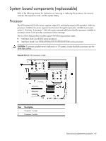
HP ML150 HP ProLiant ML150 G6 Server Maintenance and Service Guide - Page 44
Replacing the processor, HP recommends thermal grease of X-23-7783D made by Shin-Etsu.
 |
UPC - 884420743644
View all HP ML150 manuals
Add to My Manuals
Save this manual to your list of manuals |
Page 44 highlights
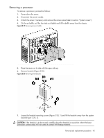
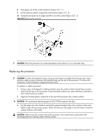
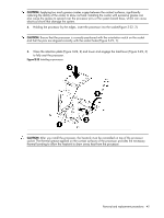
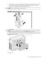
8. Disengage and lift the socket load lever (Figure 3-21, 1). 9. Lift the retention plate to expose the socket body (Figure 3-21, 2). 10. Grasp the processor by its edges and lift it out of the socket (Figure 3-21, 3). Figure 3-21 Removing the processor CAUTION: Place the processor on a static-dissipating work surface or in an anti-static bag. Replacing the processor CAUTION: To allow the heatsink to draw away as much heat as possible from the processor, there must be a tight connection between the heatsink base and the top of the processor. To ensure this connection, a thermal grease compound must be used. To replace or install a processor: 1. Using a clean cloth dipped in rubbing alcohol, clean the surface of the heatsink base (contact area) and the top of new processor. Ensure that both surfaces are clean and that no particles or dust contaminants are evident. 2. Apply the thermal grease compound to the top of the processor (the contact surface). CAUTION: HP recommends thermal grease of X-23-7783D made by Shin-Etsu. 3. Use the edge of a razor blade to spread the grease throughout the entire contact surface and lightly scrape off any excess grease. Make sure that you only apply a very thin layer so that the contact surface is still visible. CAUTION: Never touch the contact area of the processor. Any contaminant could prevent the mounting pads from making contact with the socket. Removal and replacement procedures 44
-
 1
1 -
2
-
3
-
4
-
5
-
6
-
7
-
8
-
9
-
10
-
11
-
12
-
13
-
14
-
15
-
16
-
17
-
18
-
19
-
20
-
21
-
22
-
23
-
24
-
25
-
26
-
27
-
28
-
29
-
30
-
31
-
32
-
33
-
34
-
35
-
36
-
37
-
38
-
 39
39 -
 40
40 -
 41
41 -
 42
42 -
 43
43 -
 44
44 -
 45
45 -
 46
46 -
 47
47 -
 48
48 -
 49
49 -
50
-
51
-
52
-
53
-
54
-
55
-
56
-
57
-
58
-
59
-
60
-
61
-
62
-
63
-
64
-
65
-
66
-
67
-
68
-
69
-
70
-
71
-
72
-
73
-
74
-
75
-
76
-
77
-
78
-
79
-
80
-
81
-
82
-
83
-
84
-
85
-
86
-
87
-
88
-
89
-
90
-
91
-
92
-
93
-
94
-
95
-
96
-
97
-
98
-
99
-
100
-
101
-
102
-
103
-
104
-
105
-
106
 |
 |
