HP ML150 HP ProLiant ML150 G6 Server Maintenance and Service Guide - Page 90
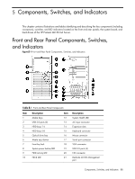
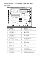
System Board Components, Switches, and Indicators
 |
UPC - 884420743644
View all HP ML150 manuals
Add to My Manuals
Save this manual to your list of manuals |
Page 90 highlights
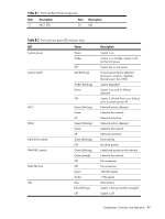
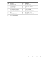
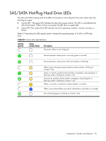
System Board Components, Switches, and Indicators Figure 5-2 System Board Components, switches, and indicators Item Description 1 Processor 1 Socket 2 CPU1_DIMM slot 1D 3 CPU1_DIMM slot 2A 4 CPU1_DIMM slot 3E 5 CPU1_DIMM slot 4B 6 CPU1_DIMM slot 5F 7 CPU1_DIMM slot 6C 8 Power supply connector (4-Pin) 9 Expansion Slot 5 10 Expansion Slot 4 11 Expansion Slot 3 12 Expansion Slot 2 13 Expansion Slot 1 14 CPU2_DIMM slot 6C 15 CPU2_DIMM slot 5F 16 CPU2_DIMM slot 4B 17 CPU2_DIMM slot 3E Item 26 27 28 29 30 31 32 33 34 35 36 37 38 39 40 41 42 Description SATA 5_ODD 1 connector SATA 4 connector SATA 3 connector SATA 2 connector SATA 1 connector System fan 1 System fan 2 (Redundant) System fan 3 System fan 4 I2C connector (2) NMI button SGPIO Front panel USB connector Internal USB port Chassis/Board ID DIP switch Front panel I/O connector Redundant power supply connector Components, Switches, and Indicators 90
-
 1
1 -
2
-
3
-
4
-
5
-
6
-
7
-
8
-
9
-
10
-
11
-
12
-
13
-
14
-
15
-
16
-
17
-
18
-
19
-
20
-
21
-
22
-
23
-
24
-
25
-
26
-
27
-
28
-
29
-
30
-
31
-
32
-
33
-
34
-
35
-
36
-
37
-
38
-
39
-
40
-
41
-
42
-
43
-
44
-
45
-
46
-
47
-
48
-
49
-
50
-
51
-
52
-
53
-
54
-
55
-
56
-
57
-
58
-
59
-
60
-
61
-
62
-
63
-
64
-
65
-
66
-
67
-
68
-
69
-
70
-
71
-
72
-
73
-
74
-
75
-
76
-
77
-
78
-
79
-
80
-
81
-
82
-
83
-
84
-
 85
85 -
 86
86 -
 87
87 -
 88
88 -
 89
89 -
 90
90 -
 91
91 -
 92
92 -
 93
93 -
 94
94 -
 95
95 -
96
-
97
-
98
-
99
-
100
-
101
-
102
-
103
-
104
-
105
-
106
 |
 |
