HP ML150 HP ProLiant ML150 G6 Server Maintenance and Service Guide - Page 57
Rear fan assembly removal and replacement, Remove the 2 screws
 |
UPC - 884420743644
View all HP ML150 manuals
Add to My Manuals
Save this manual to your list of manuals |
Page 57 highlights
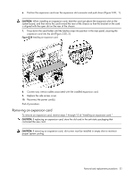
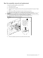
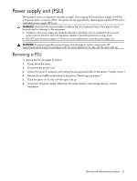
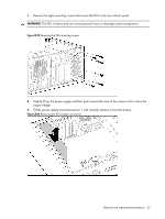
Rear fan assembly removal and replacement To remove the rear fan assembly, proceed as follows: 1. Power down the server. 2. Disconnect the power cord(s). 3. Unlock the server if necessary and remove the access panel as described in the section "System covers." 4. Remove the air baffle as described in the section "Removing a processor." 5. Remove the 2 screws (Figure 3-35, 1) and take off the rear fan (Figure 3-35, 2). WARNING: Be sure to support the fan with your hands when removing it from the chassis. The fan could fall and cause personal injury or equipment damage if not supported. 6. Disconnect the fan cable from the system board connector (Figure 3-35, 3). Figure 3-36 Removing the rear chassis fan assembly 7. Lift the fan assembly away from the rear panel and from the chassis. Removal and replacement procedures 57
-
 1
1 -
2
-
3
-
4
-
5
-
6
-
7
-
8
-
9
-
10
-
11
-
12
-
13
-
14
-
15
-
16
-
17
-
18
-
19
-
20
-
21
-
22
-
23
-
24
-
25
-
26
-
27
-
28
-
29
-
30
-
31
-
32
-
33
-
34
-
35
-
36
-
37
-
38
-
39
-
40
-
41
-
42
-
43
-
44
-
45
-
46
-
47
-
48
-
49
-
50
-
51
-
 52
52 -
 53
53 -
 54
54 -
 55
55 -
 56
56 -
 57
57 -
 58
58 -
 59
59 -
 60
60 -
 61
61 -
 62
62 -
63
-
64
-
65
-
66
-
67
-
68
-
69
-
70
-
71
-
72
-
73
-
74
-
75
-
76
-
77
-
78
-
79
-
80
-
81
-
82
-
83
-
84
-
85
-
86
-
87
-
88
-
89
-
90
-
91
-
92
-
93
-
94
-
95
-
96
-
97
-
98
-
99
-
100
-
101
-
102
-
103
-
104
-
105
-
106
 |
 |
