IBM 7379E2U User Manual - Page 101
Installing an optional ServeRAID adapter advanced feature key
 |
View all IBM 7379E2U manuals
Add to My Manuals
Save this manual to your list of manuals |
Page 101 highlights
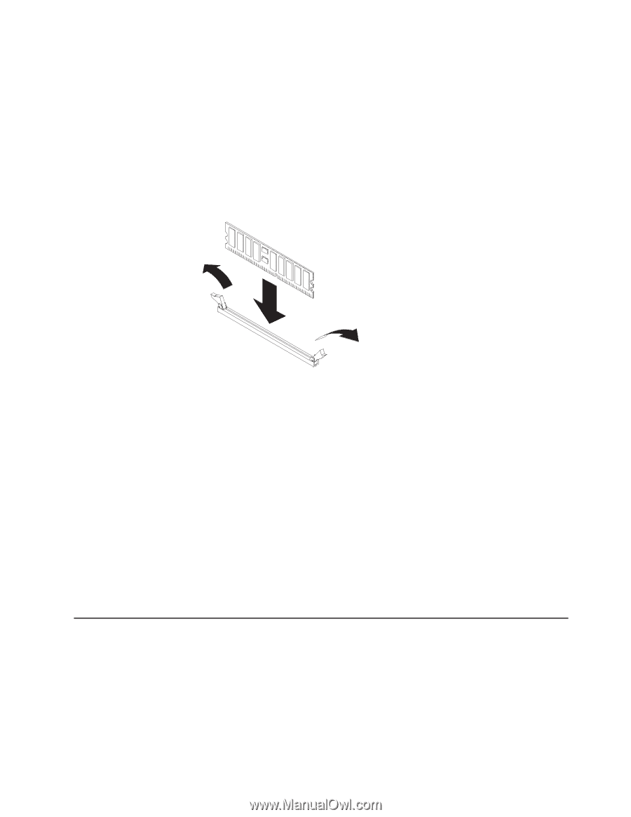
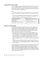
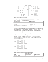
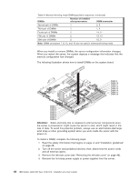
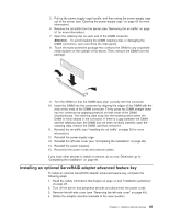
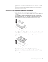
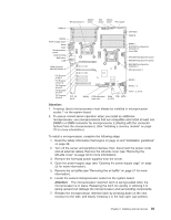
5. Pull up the power-supply cage handle, and then swing the power-supply cage out of the server (see "Opening the power-supply cage" on page 55 for more information). 6. Remove the air baffle from the server (see "Removing the air baffle" on page 51 for more information). 7. Open the retaining clip on each end of the DIMM connector. Attention: To avoid breaking the DIMM retaining clips or damaging the DIMM connectors, open and close the clips gently. 8. Touch the static-protective package that contains the DIMM to any unpainted metal surface on the outside of the server. Then, remove the DIMM from the package. 9. Turn the DIMM so that the DIMM keys align correctly with the connector. 10. Insert the DIMM into the connector by aligning the edges of the DIMM with the slots at the ends of the DIMM connector. Firmly press the DIMM straight down into the connector by applying pressure on both ends of the DIMM simultaneously. The retaining clips snap into the locked position when the DIMM is firmly seated in the connector. If there is a gap between the DIMM and the retaining clips, the DIMM has not been correctly inserted; open the retaining clips, remove the DIMM, and then reinsert it. 11. Reinstall the air baffle (see "Installing the air baffle" on page 52 for more information). 12. Reinstall the power-supply cage. 13. Reinstall the left-side cover (see "Completing the installation" on page 96). 14. Reinstall the power supplies. 15. Reconnect the power cords and external cables. If you have other devices to install or remove, do so now. Otherwise, go to "Completing the installation" on page 96. Installing an optional ServeRAID adapter advanced feature key To install an optional ServeRAID adapter advanced feature key, complete the following steps: 1. Read the safety information that begins on page vii and "Installation guidelines" on page 28. 2. Turn off the server and peripheral devices and disconnect the power cords. 3. Remove the left-side cover (see "Removing the left-side cover" on page 48). 4. Rotate the adapter-retention brackets to the open position. Chapter 2. Installing optional devices 85
-
 1
1 -
2
-
3
-
4
-
5
-
6
-
7
-
8
-
9
-
10
-
11
-
12
-
13
-
14
-
15
-
16
-
17
-
18
-
19
-
20
-
21
-
22
-
23
-
24
-
25
-
26
-
27
-
28
-
29
-
30
-
31
-
32
-
33
-
34
-
35
-
36
-
37
-
38
-
39
-
40
-
41
-
42
-
43
-
44
-
45
-
46
-
47
-
48
-
49
-
50
-
51
-
52
-
53
-
54
-
55
-
56
-
57
-
58
-
59
-
60
-
61
-
62
-
63
-
64
-
65
-
66
-
67
-
68
-
69
-
70
-
71
-
72
-
73
-
74
-
75
-
76
-
77
-
78
-
79
-
80
-
81
-
82
-
83
-
84
-
85
-
86
-
87
-
88
-
89
-
90
-
91
-
92
-
93
-
94
-
95
-
 96
96 -
 97
97 -
 98
98 -
 99
99 -
 100
100 -
 101
101 -
 102
102 -
 103
103 -
 104
104 -
 105
105 -
 106
106 -
107
-
108
-
109
-
110
-
111
-
112
-
113
-
114
-
115
-
116
-
117
-
118
-
119
-
120
-
121
-
122
-
123
-
124
-
125
-
126
-
127
-
128
-
129
-
130
-
131
-
132
-
133
-
134
-
135
-
136
-
137
-
138
-
139
-
140
-
141
-
142
-
143
-
144
-
145
-
146
-
147
-
148
-
149
-
150
-
151
-
152
 |
 |