IBM 7379E2U User Manual - Page 43
Operator information panel, Lit light path diagnostics LED with
 |
View all IBM 7379E2U manuals
Add to My Manuals
Save this manual to your list of manuals |
Page 43 highlights
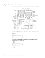
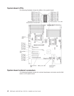
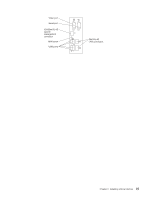
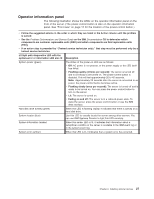
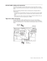
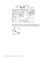
Operator information panel The following illustration shows the LEDs on the operator information panel on the front of the server. (The power-control button is also on the operator information panel. See "Front view" on page 12 for the location of the power-control button.) v Follow the suggested actions in the order in which they are listed in the Action column until the problem is solved. v See the Problem Determination and Service Guide on the IBM Documentation CD to determine which components are customer replaceable units (CRU) and which components are field replaceable units (FRU). v If an action step is preceded by "(Trained service technician only)," that step must be performed only by a trained service technician. Lit light path diagnostics LED with the system-error or information LED also lit Description System power (green) The states of the power-on LED are as follows: v Off: AC power is not present, or the power supply or the LED itself has failed. v Flashing rapidly (4 times per second): The server is turned off and is not ready to be turned on. The power-control button is disabled. This will last approximately 20 to 40 seconds. Note: Approximately 20 seconds after the server is connected to ac power, the power-control button becomes active. v Flashing slowly (once per second): The server is turned off and is ready to be turned on. You can press the power-control button to turn on the server. v Lit: The server is turned on. v Fading on and off: The server is in a reduced-power state. To wake the server, press the power-control button or use the IMM Web interface. Hard disk drive activity (green) When this LED is flashing rapidly, it indicates that there is activity on a hard disk drive. System locator (blue) Use this LED to visually locate the server among other servers. You can use IBM Systems Director to light this LED remotely. System information (amber) When this amber LED is lit, it indicates that information about a suboptimal condition in the server is available in the IMM event log or in the system-event log. System error (amber) When this LED is lit, it indicates that a system error has occurred. Chapter 2. Installing optional devices 27
-
 1
1 -
2
-
3
-
4
-
5
-
6
-
7
-
8
-
9
-
10
-
11
-
12
-
13
-
14
-
15
-
16
-
17
-
18
-
19
-
20
-
21
-
22
-
23
-
24
-
25
-
26
-
27
-
28
-
29
-
30
-
31
-
32
-
33
-
34
-
35
-
36
-
37
-
 38
38 -
 39
39 -
 40
40 -
 41
41 -
 42
42 -
 43
43 -
 44
44 -
 45
45 -
 46
46 -
 47
47 -
 48
48 -
49
-
50
-
51
-
52
-
53
-
54
-
55
-
56
-
57
-
58
-
59
-
60
-
61
-
62
-
63
-
64
-
65
-
66
-
67
-
68
-
69
-
70
-
71
-
72
-
73
-
74
-
75
-
76
-
77
-
78
-
79
-
80
-
81
-
82
-
83
-
84
-
85
-
86
-
87
-
88
-
89
-
90
-
91
-
92
-
93
-
94
-
95
-
96
-
97
-
98
-
99
-
100
-
101
-
102
-
103
-
104
-
105
-
106
-
107
-
108
-
109
-
110
-
111
-
112
-
113
-
114
-
115
-
116
-
117
-
118
-
119
-
120
-
121
-
122
-
123
-
124
-
125
-
126
-
127
-
128
-
129
-
130
-
131
-
132
-
133
-
134
-
135
-
136
-
137
-
138
-
139
-
140
-
141
-
142
-
143
-
144
-
145
-
146
-
147
-
148
-
149
-
150
-
151
-
152
 |
 |