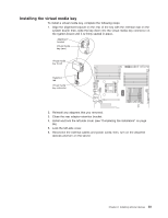
IBM 7379E2U User Manual - Page 99
The following table lists the DIMM connectors on each memory channel., and 6
 |
View all IBM 7379E2U manuals
Add to My Manuals
Save this manual to your list of manuals |
Page 99 highlights
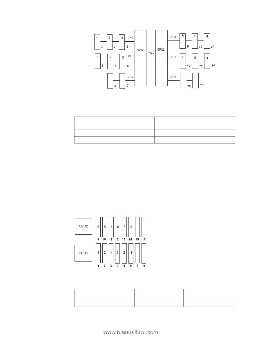
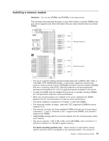
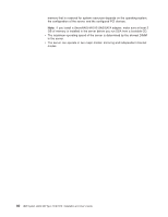
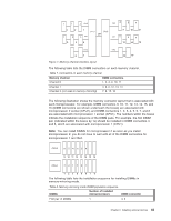
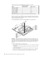
Figure 7. Memory channel interface layout The following table lists the DIMM connectors on each memory channel. Table 7. Connectors on each memory channel Memory channel Channel 0 DIMM connectors 1, 2, 3, 9, 10, 11 Channel 1 4, 5, 6, 12, 13, 14 Channel 2 (not used in memory mirroring) 7, 8, 15, 16 The following illustration shows the memory connector layout that is associated with each microprocessor. For example, DIMM connectors 9, 10, 11, 12, 13, 14, 15, and 16 (DIMM connectors are shown underneath the boxes) are associated with microprocessor 2 socket (CPU2), and DIMM connectors 1, 2, 3, 4, 5, 6, 7, and 8 are associated with microprocessor 1 socket (CPU1). The numbers within the boxes indicate the installation sequence of the DIMM pairs. For example, the first DIMM pair (indicated within the boxes by 1s) should be installed in DIMM connectors 3 and 6, which are associated with microprocessor 1 (CPU1). Note: You can install DIMMs for microprocessor 2 as soon as you install microprocessor 2; you do not have to wait until all of the DIMM connectors for microprocessor 1 are filled. The following table lists the installation sequence for installing DIMMs in memory-mirroring mode. Table 8. Memory-mirroring mode DIMM population sequence DIMMs Number of installed microprocessors DIMM connector First pair of DIMMs 1 3, 6 Chapter 2. Installing optional devices 83
-
 1
1 -
2
-
3
-
4
-
5
-
6
-
7
-
8
-
9
-
10
-
11
-
12
-
13
-
14
-
15
-
16
-
17
-
18
-
19
-
20
-
21
-
22
-
23
-
24
-
25
-
26
-
27
-
28
-
29
-
30
-
31
-
32
-
33
-
34
-
35
-
36
-
37
-
38
-
39
-
40
-
41
-
42
-
43
-
44
-
45
-
46
-
47
-
48
-
49
-
50
-
51
-
52
-
53
-
54
-
55
-
56
-
57
-
58
-
59
-
60
-
61
-
62
-
63
-
64
-
65
-
66
-
67
-
68
-
69
-
70
-
71
-
72
-
73
-
74
-
75
-
76
-
77
-
78
-
79
-
80
-
81
-
82
-
83
-
84
-
85
-
86
-
87
-
88
-
89
-
90
-
91
-
92
-
93
-
 94
94 -
 95
95 -
 96
96 -
 97
97 -
 98
98 -
 99
99 -
 100
100 -
 101
101 -
 102
102 -
 103
103 -
 104
104 -
105
-
106
-
107
-
108
-
109
-
110
-
111
-
112
-
113
-
114
-
115
-
116
-
117
-
118
-
119
-
120
-
121
-
122
-
123
-
124
-
125
-
126
-
127
-
128
-
129
-
130
-
131
-
132
-
133
-
134
-
135
-
136
-
137
-
138
-
139
-
140
-
141
-
142
-
143
-
144
-
145
-
146
-
147
-
148
-
149
-
150
-
151
-
152
 |
 |