IBM 7379E2U User Manual - Page 32
Power-supply LEDs, USB connectors, Ethernet connectors, Ethernet transmit/receive activity LED
 |
View all IBM 7379E2U manuals
Add to My Manuals
Save this manual to your list of manuals |
Page 32 highlights
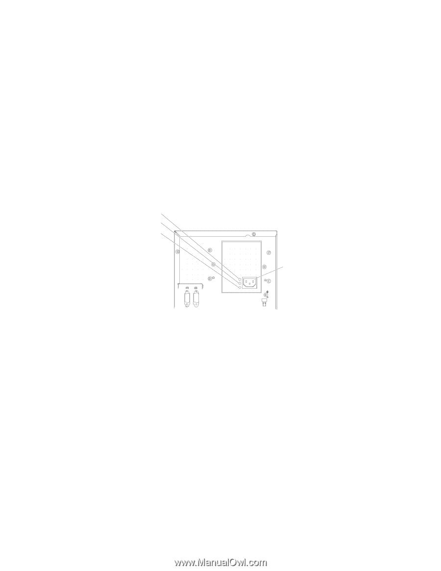
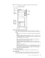
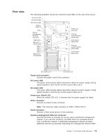
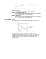
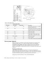
from the production network. You can use the Setup utility to configure the server to use a dedicated systems management network or a shared network. USB connectors Connect USB devices to these connectors. Ethernet connectors Use theses connectors to connect the server to a network. Ethernet transmit/receive activity LED This LED is on the Ethernet connector. When this LED is lit, it indicates that there is activity between the server and the network. Ethernet link status LED This LED is on the Ethernet connector. When this LED is lit, it indicates that there is an active connection on the Ethernet port. Power-supply LEDs The following illustration shows the locations of the 670-watt power supply LEDs. AC power LED DC power LED Fault (error) LED Power cord connector The following table describes the problems that are indicated by various combinations of the power-supply LEDs and the power-on LED on the operator information panel and suggested actions to correct the detected problems. (See "Operator information panel" on page 27 for information about the operator information panel.) 16 IBM System x3400 M3 Type 7378/7379: Installation and User's Guide
-
 1
1 -
2
-
3
-
4
-
5
-
6
-
7
-
8
-
9
-
10
-
11
-
12
-
13
-
14
-
15
-
16
-
17
-
18
-
19
-
20
-
21
-
22
-
23
-
24
-
25
-
26
-
 27
27 -
 28
28 -
 29
29 -
 30
30 -
 31
31 -
 32
32 -
 33
33 -
 34
34 -
 35
35 -
 36
36 -
 37
37 -
38
-
39
-
40
-
41
-
42
-
43
-
44
-
45
-
46
-
47
-
48
-
49
-
50
-
51
-
52
-
53
-
54
-
55
-
56
-
57
-
58
-
59
-
60
-
61
-
62
-
63
-
64
-
65
-
66
-
67
-
68
-
69
-
70
-
71
-
72
-
73
-
74
-
75
-
76
-
77
-
78
-
79
-
80
-
81
-
82
-
83
-
84
-
85
-
86
-
87
-
88
-
89
-
90
-
91
-
92
-
93
-
94
-
95
-
96
-
97
-
98
-
99
-
100
-
101
-
102
-
103
-
104
-
105
-
106
-
107
-
108
-
109
-
110
-
111
-
112
-
113
-
114
-
115
-
116
-
117
-
118
-
119
-
120
-
121
-
122
-
123
-
124
-
125
-
126
-
127
-
128
-
129
-
130
-
131
-
132
-
133
-
134
-
135
-
136
-
137
-
138
-
139
-
140
-
141
-
142
-
143
-
144
-
145
-
146
-
147
-
148
-
149
-
150
-
151
-
152
 |
 |