IBM 7379E2U User Manual - Page 98
Independent channel mode, Memory-mirroring mode
 |
View all IBM 7379E2U manuals
Add to My Manuals
Save this manual to your list of manuals |
Page 98 highlights
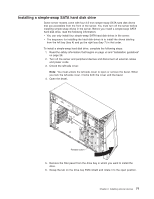
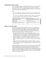
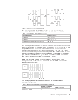
Independent channel mode The server requires at least one installed DIMM. The server comes with a minimum of two 1 GB DIMMs, installed in connectors 3 and 6. Connector 3 (in channel 0) and connector 6 (in channel 1) are the farthest connectors from microprocessor 1 in those channels. When you install additional DIMMs, install them in the order shown in Table 6, to maintain server performance. Note: v If you have configured the server to use memory mirroring, do not use the order shown in this table; use the installation order that is shown in Table 8 on page 83. v If you install a ServeRAID-M1015 SAS/SATA adapter, make sure at least 2 GB of memory is installed in the server before you run DSA from a bootable CD. Table 6. DIMM installation sequence for independent channel mode Installed microprocessors DIMM connector population sequence Microprocessor 1 3, 6, 8, 2, 5, 7, 1, 4 Microprocessor 2 11, 14, 16, 10, 13, 15, 9, 12 Microprocessor 1 and Microprocessor 2 3, 11, 6, 14, 8, 16, 2, 10, 5, 13, 7, 15, 1, 9, 4, 12 Memory-mirroring mode Memory-mirroring mode replicates and stores data on two pairs of DIMMs within two channels simultaneously. If a failure occurs, the memory controller switches from the primary pair of memory DIMMs to the backup pair of DIMMs. You must enable memory mirroring through the Setup utility. For details about enabling memory mirroring, see "Using the Setup utility" on page 100. When you use the memory-mirroring feature, consider the following information: v When you use memory mirroring, you must install a pair of DIMMs at a time. One DIMM must be in channel 0, and the mirroring DIMM must be in the same connector in channel 1. The two DIMMs in each pair must be identical in size, type, rank (single or dual), and organization. They do not have to be identical in speed. The channels run at the speed of the slowest DIMM in any of the channels. See Table 8 on page 83 for the DIMM connectors that are in each pair. v Channel 2, DIMM connectors 7, 8, 15, and 16 are not used in memory-mirroring mode. v The maximum amount of available memory is reduced to half of the amount of installed memory when memory mirroring is enabled. For example, if you install 64 GB of memory, only 32 GB of addressable memory is available when you use memory mirroring. The following illustration shows the memory channel interface layout with the DIMM installation sequence for memory-mirroring mode. The numbers within the boxes indicate the DIMM population sequence in pairs within the channels, and the numbers next to the boxes indicate the DIMM connectors within the channels. For example, the following illustration shows that the first pair of DIMMs (indicated by 1s inside the boxes) should be installed in DIMM connector 3 on channel 0 and DIMM connector 6 on channel 1. DIMM connectors 7, 8, 15, and 16 on channel 2 are not used in memory-mirroring mode. 82 IBM System x3400 M3 Type 7378/7379: Installation and User's Guide
-
 1
1 -
2
-
3
-
4
-
5
-
6
-
7
-
8
-
9
-
10
-
11
-
12
-
13
-
14
-
15
-
16
-
17
-
18
-
19
-
20
-
21
-
22
-
23
-
24
-
25
-
26
-
27
-
28
-
29
-
30
-
31
-
32
-
33
-
34
-
35
-
36
-
37
-
38
-
39
-
40
-
41
-
42
-
43
-
44
-
45
-
46
-
47
-
48
-
49
-
50
-
51
-
52
-
53
-
54
-
55
-
56
-
57
-
58
-
59
-
60
-
61
-
62
-
63
-
64
-
65
-
66
-
67
-
68
-
69
-
70
-
71
-
72
-
73
-
74
-
75
-
76
-
77
-
78
-
79
-
80
-
81
-
82
-
83
-
84
-
85
-
86
-
87
-
88
-
89
-
90
-
91
-
92
-
 93
93 -
 94
94 -
 95
95 -
 96
96 -
 97
97 -
 98
98 -
 99
99 -
 100
100 -
 101
101 -
 102
102 -
 103
103 -
104
-
105
-
106
-
107
-
108
-
109
-
110
-
111
-
112
-
113
-
114
-
115
-
116
-
117
-
118
-
119
-
120
-
121
-
122
-
123
-
124
-
125
-
126
-
127
-
128
-
129
-
130
-
131
-
132
-
133
-
134
-
135
-
136
-
137
-
138
-
139
-
140
-
141
-
142
-
143
-
144
-
145
-
146
-
147
-
148
-
149
-
150
-
151
-
152
 |
 |