IBM 7379E2U User Manual - Page 108
Turn the VRM so that the keys align with the connector.
 |
View all IBM 7379E2U manuals
Add to My Manuals
Save this manual to your list of manuals |
Page 108 highlights
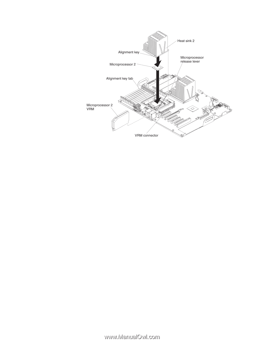
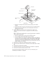
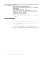
d. Slide the rear flange of the heat sink into the opening in the retainer bracket. e. Press down firmly on the front of the heat sink until it is seated securely. f. Rotate the heat-sink release lever to the closed position and hook it underneath the lock tab. 13. Install a VRM in the connector next to microprocessor socket 2 (see "System-board internal connectors" on page 22 for the VRM connector location). Note: A VRM must be installed when a second microprocessor is installed in order to power on the server. a. Open the retaining clips on each end of the VRM connector. b. Turn the VRM so that the keys align with the connector. c. Insert the VRM into the connector by aligning the edges of the VRM with the slots at the end of the VRM connector. Firmly press the VRM straight down into the connector by applying pressure on both ends of the VRM simultaneously. The retaining clips snap into the locked position when the VRM is seated in the connector. 14. Reinstall the air baffle (see "Installing the air baffle" on page 52). 15. Close the power-supply cage (see "Closing the power-supply cage" on page 56). 16. Reinstall the hot-swap power supplies. 17. Reinstall the left-side cover (see "Completing the installation" on page 96). 18. Reconnect the external cables and power cords. If you have other devices to install or remove, do so now. Otherwise, go to "Completing the installation" on page 96. 92 IBM System x3400 M3 Type 7378/7379: Installation and User's Guide
-
 1
1 -
2
-
3
-
4
-
5
-
6
-
7
-
8
-
9
-
10
-
11
-
12
-
13
-
14
-
15
-
16
-
17
-
18
-
19
-
20
-
21
-
22
-
23
-
24
-
25
-
26
-
27
-
28
-
29
-
30
-
31
-
32
-
33
-
34
-
35
-
36
-
37
-
38
-
39
-
40
-
41
-
42
-
43
-
44
-
45
-
46
-
47
-
48
-
49
-
50
-
51
-
52
-
53
-
54
-
55
-
56
-
57
-
58
-
59
-
60
-
61
-
62
-
63
-
64
-
65
-
66
-
67
-
68
-
69
-
70
-
71
-
72
-
73
-
74
-
75
-
76
-
77
-
78
-
79
-
80
-
81
-
82
-
83
-
84
-
85
-
86
-
87
-
88
-
89
-
90
-
91
-
92
-
93
-
94
-
95
-
96
-
97
-
98
-
99
-
100
-
101
-
102
-
 103
103 -
 104
104 -
 105
105 -
 106
106 -
 107
107 -
 108
108 -
 109
109 -
 110
110 -
 111
111 -
 112
112 -
 113
113 -
114
-
115
-
116
-
117
-
118
-
119
-
120
-
121
-
122
-
123
-
124
-
125
-
126
-
127
-
128
-
129
-
130
-
131
-
132
-
133
-
134
-
135
-
136
-
137
-
138
-
139
-
140
-
141
-
142
-
143
-
144
-
145
-
146
-
147
-
148
-
149
-
150
-
151
-
152
 |
 |