IBM 7379E2U User Manual - Page 105
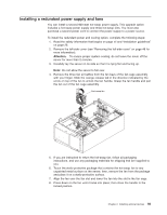
Remove the hot-swap power supplies from the server., left-side cover on for more information.
 |
View all IBM 7379E2U manuals
Add to My Manuals
Save this manual to your list of manuals |
Page 105 highlights
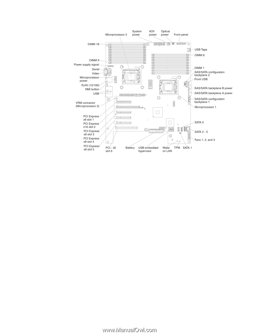
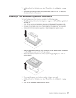
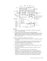
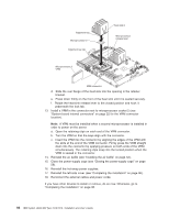
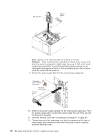
Attention: 1. A startup (boot) microprocessor must always be installed in microprocessor socket 1 on the system board. 2. To ensure correct server operation when you install an additional microprocessor, use microprocessors that are compatible and install at least one DIMM in a DIMM connector for microprocessor 2 (starting with the connector farthest from the microprocessor). (See "Installing a memory module" on page 79 for more information.) To install a microprocessor, complete the following steps: 1. Read the safety information that begins on page vii and "Installation guidelines" on page 28. 2. Turn off the server and peripheral devices; then, disconnect the power cords and all external cables. Remove the left-side cover (see "Removing the left-side cover" on page 48 for more information). 3. Remove the hot-swap power supplies from the server. 4. Open the power-supply cage (see "Opening the power-supply cage" on page 55 for more information). 5. Remove the air baffle (see "Removing the air baffle" on page 51 for more information). 6. Locate the second microprocessor socket on the system board. Attention: The microprocessor retention latch is spring-loaded when the microprocessor is in place. Releasing the latch too quickly or allowing it to spring upward can damage the microprocessor and surrounding components. 7. Release the microprocessor retention latch by pressing down on the end, moving it to the side, and slowly releasing it to the fully open (up) position. Chapter 2. Installing optional devices 89
-
 1
1 -
2
-
3
-
4
-
5
-
6
-
7
-
8
-
9
-
10
-
11
-
12
-
13
-
14
-
15
-
16
-
17
-
18
-
19
-
20
-
21
-
22
-
23
-
24
-
25
-
26
-
27
-
28
-
29
-
30
-
31
-
32
-
33
-
34
-
35
-
36
-
37
-
38
-
39
-
40
-
41
-
42
-
43
-
44
-
45
-
46
-
47
-
48
-
49
-
50
-
51
-
52
-
53
-
54
-
55
-
56
-
57
-
58
-
59
-
60
-
61
-
62
-
63
-
64
-
65
-
66
-
67
-
68
-
69
-
70
-
71
-
72
-
73
-
74
-
75
-
76
-
77
-
78
-
79
-
80
-
81
-
82
-
83
-
84
-
85
-
86
-
87
-
88
-
89
-
90
-
91
-
92
-
93
-
94
-
95
-
96
-
97
-
98
-
99
-
 100
100 -
 101
101 -
 102
102 -
 103
103 -
 104
104 -
 105
105 -
 106
106 -
 107
107 -
 108
108 -
 109
109 -
 110
110 -
111
-
112
-
113
-
114
-
115
-
116
-
117
-
118
-
119
-
120
-
121
-
122
-
123
-
124
-
125
-
126
-
127
-
128
-
129
-
130
-
131
-
132
-
133
-
134
-
135
-
136
-
137
-
138
-
139
-
140
-
141
-
142
-
143
-
144
-
145
-
146
-
147
-
148
-
149
-
150
-
151
-
152
 |
 |