IBM 7379E2U User Manual - Page 31
Rear view, Power-cord connector, AC power LED, Power-error Fault LED, Video connector
 |
View all IBM 7379E2U manuals
Add to My Manuals
Save this manual to your list of manuals |
Page 31 highlights
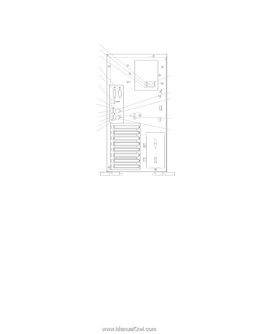
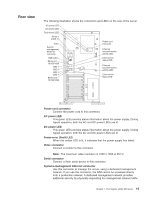
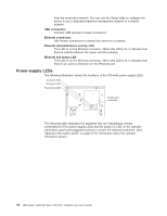
Rear view The following illustration shows the connectors and LEDs on the rear of the server. AC power LED DC power LED Fault (error) LED Serial 1 (COM 1) Video System management Ethernet connector NMI button Ethernet 1 10/100/1000 USB 1 USB 2 USB 3 USB 4 Ethernet 2 10/100/1000 Power cord connector Ethernet transmit/receive activity LED Ethernet link status LED Ethernet transmit/receive activity LED Ethernet link status LED Power-cord connector Connect the power cord to this connector. AC power LED This green LED provides status information about the power supply. During typical operation, both the AC and DC power LEDs are lit. DC power LED This green LED provides status information about the power supply. During typical operation, both the AC and DC power LEDs are lit. Power-error (Fault) LED When this amber LED is lit, it indicates that the power supply has failed. Video connector Connect a monitor to this connector. Note: The maximum video resolution is 1600 x 1200 at 85 Hz. Serial connector Connect a 9-pin serial device to this connector. Systems-mamagement Ethernet connector Use this connector to manage the server, using a dedicated management network. If you use this connector, the IMM cannot be accessed directly from a production network. A dedicated management network provides additional security by physically separating the management network traffic Chapter 1. The System x3400 M3 server 15
-
 1
1 -
2
-
3
-
4
-
5
-
6
-
7
-
8
-
9
-
10
-
11
-
12
-
13
-
14
-
15
-
16
-
17
-
18
-
19
-
20
-
21
-
22
-
23
-
24
-
25
-
 26
26 -
 27
27 -
 28
28 -
 29
29 -
 30
30 -
 31
31 -
 32
32 -
 33
33 -
 34
34 -
 35
35 -
 36
36 -
37
-
38
-
39
-
40
-
41
-
42
-
43
-
44
-
45
-
46
-
47
-
48
-
49
-
50
-
51
-
52
-
53
-
54
-
55
-
56
-
57
-
58
-
59
-
60
-
61
-
62
-
63
-
64
-
65
-
66
-
67
-
68
-
69
-
70
-
71
-
72
-
73
-
74
-
75
-
76
-
77
-
78
-
79
-
80
-
81
-
82
-
83
-
84
-
85
-
86
-
87
-
88
-
89
-
90
-
91
-
92
-
93
-
94
-
95
-
96
-
97
-
98
-
99
-
100
-
101
-
102
-
103
-
104
-
105
-
106
-
107
-
108
-
109
-
110
-
111
-
112
-
113
-
114
-
115
-
116
-
117
-
118
-
119
-
120
-
121
-
122
-
123
-
124
-
125
-
126
-
127
-
128
-
129
-
130
-
131
-
132
-
133
-
134
-
135
-
136
-
137
-
138
-
139
-
140
-
141
-
142
-
143
-
144
-
145
-
146
-
147
-
148
-
149
-
150
-
151
-
152
 |
 |