IBM 7379E2U User Manual - Page 113
Updating the server configuration
 |
View all IBM 7379E2U manuals
Add to My Manuals
Save this manual to your list of manuals |
Page 113 highlights
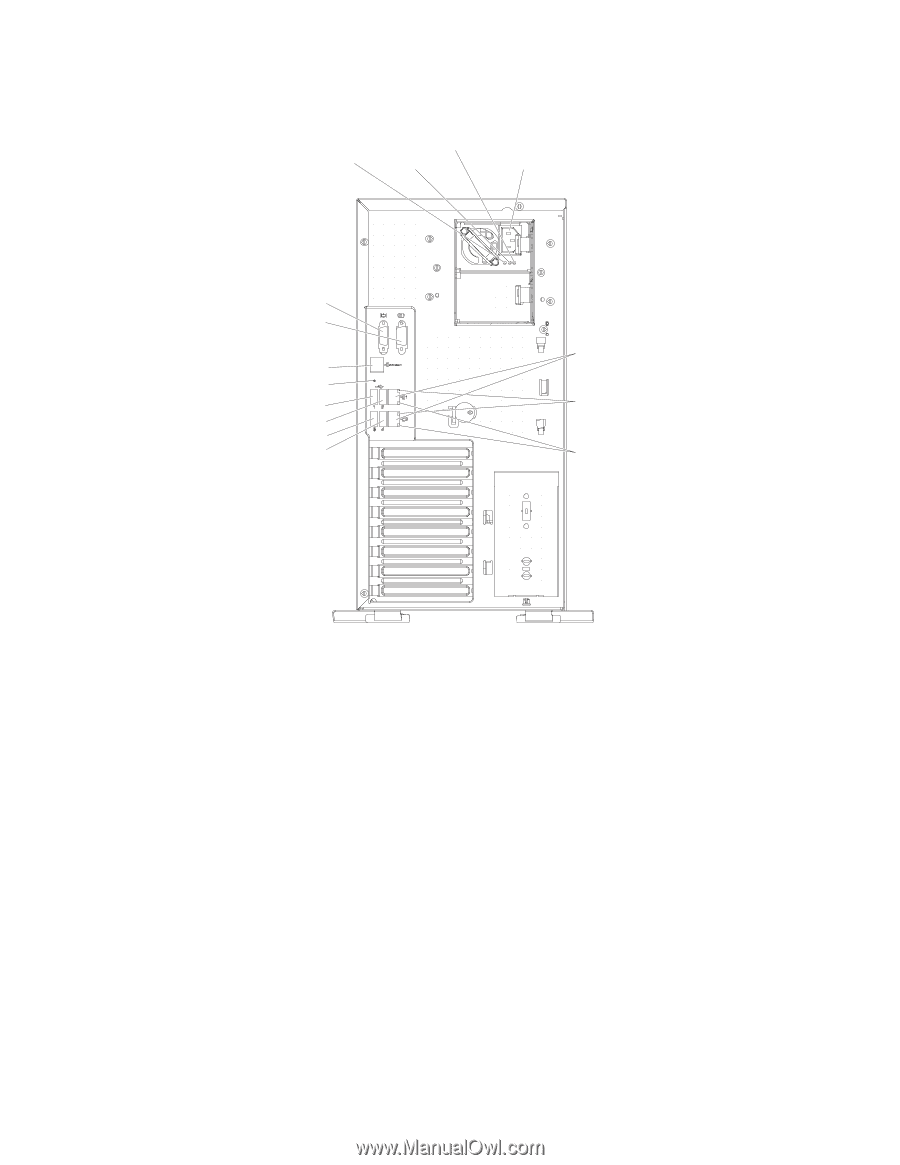
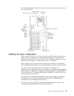
The following illustration shows the locations of the input and output connectors on the rear of the server. AC power LED Power error LED Power cord DC power LED connector Video Serial 1 (COM 1) Systems management NMI button USB 1 USB 2 USB 3 USB 4 Ethernet 10/100/1000 Ethernet transmit/receive activity LEDs Ethernet link status LEDs Updating the server configuration When you start the server for the first time after you add or remove a device, you might receive a message that the configuration has changed. The Setup utility starts automatically so that you can save the new configuration settings. For more information, see Chapter 3, "Configuring the server," on page 99. Some optional devices have device drivers that you must install. For information about installing device drivers, see the documentation that comes with each device. The server comes with at least one microprocessor. If more than one microprocessor is installed, the server can operate as a symmetric multiprocessing (SMP) server. You might have to upgrade the operating system to support SMP. For more information, see "Typical operating-system installation" on page 109 and the operating-system documentation. If the server has an optional RAID adapter and you have installed or removed a hard disk drive, see the documentation that comes with the RAID adapter for information about reconfiguring the disk arrays. For information about configuring the integrated Gigabit Ethernet controller, see "Configuring the Gigabit Ethernet controller" on page 113. Chapter 2. Installing optional devices 97
-
 1
1 -
2
-
3
-
4
-
5
-
6
-
7
-
8
-
9
-
10
-
11
-
12
-
13
-
14
-
15
-
16
-
17
-
18
-
19
-
20
-
21
-
22
-
23
-
24
-
25
-
26
-
27
-
28
-
29
-
30
-
31
-
32
-
33
-
34
-
35
-
36
-
37
-
38
-
39
-
40
-
41
-
42
-
43
-
44
-
45
-
46
-
47
-
48
-
49
-
50
-
51
-
52
-
53
-
54
-
55
-
56
-
57
-
58
-
59
-
60
-
61
-
62
-
63
-
64
-
65
-
66
-
67
-
68
-
69
-
70
-
71
-
72
-
73
-
74
-
75
-
76
-
77
-
78
-
79
-
80
-
81
-
82
-
83
-
84
-
85
-
86
-
87
-
88
-
89
-
90
-
91
-
92
-
93
-
94
-
95
-
96
-
97
-
98
-
99
-
100
-
101
-
102
-
103
-
104
-
105
-
106
-
107
-
 108
108 -
 109
109 -
 110
110 -
 111
111 -
 112
112 -
 113
113 -
 114
114 -
 115
115 -
 116
116 -
 117
117 -
 118
118 -
119
-
120
-
121
-
122
-
123
-
124
-
125
-
126
-
127
-
128
-
129
-
130
-
131
-
132
-
133
-
134
-
135
-
136
-
137
-
138
-
139
-
140
-
141
-
142
-
143
-
144
-
145
-
146
-
147
-
148
-
149
-
150
-
151
-
152
 |
 |