IBM HC10 Service Guide - Page 37
Removing, bezel, assembly, Installing
 |
UPC - 883436017671
View all IBM HC10 manuals
Add to My Manuals
Save this manual to your list of manuals |
Page 37 highlights
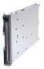
Removing the bezel assembly To remove the bezel assembly, complete the following steps. Bezel-assembly release Bezel-assembly release Bezel Control-panel cable Control-panel connector 1. Read the safety information that begins on page vii and "Installation guidelines" on page 13. 2. If the blade workstation is installed in a BladeCenter unit, remove it (see "Removing the blade workstation from a BladeCenter unit" on page 16 for instructions). 3. Open the blade workstation cover (see "Removing the blade workstation cover" on page 19 for instructions). 4. Press the bezel-assembly release on each side of the blade workstation and pull the bezel assembly away from the blade workstation approximately 1.2 cm (0.5 inch). 5. Disconnect the control-panel cable from the control-panel connector. 6. Pull the bezel assembly away from the blade workstation. 7. Store the bezel assembly in a safe place. Installing the bezel assembly To install the bezel assembly, complete the following steps. Bezel-assembly release Bezel-assembly release Bezel Control-panel cable Control-panel connector 1. Read the safety information that begins on page vii and "Installation guidelines" on page 13. 2. Connect the control-panel cable to the control-panel connector on the system board. Chapter 4. Removing and replacing blade workstation components 21
-
 1
1 -
2
-
3
-
4
-
5
-
6
-
7
-
8
-
9
-
10
-
11
-
12
-
13
-
14
-
15
-
16
-
17
-
18
-
19
-
20
-
21
-
22
-
23
-
24
-
25
-
26
-
27
-
28
-
29
-
30
-
31
-
 32
32 -
 33
33 -
 34
34 -
 35
35 -
 36
36 -
 37
37 -
 38
38 -
 39
39 -
 40
40 -
 41
41 -
 42
42 -
43
-
44
-
45
-
46
-
47
-
48
-
49
-
50
-
51
-
52
-
53
-
54
-
55
-
56
-
57
-
58
-
59
-
60
-
61
-
62
-
63
-
64
-
65
-
66
-
67
-
68
-
69
-
70
-
71
-
72
-
73
-
74
-
75
-
76
-
77
-
78
-
79
-
80
-
81
-
82
-
83
-
84
-
85
-
86
-
87
-
88
-
89
-
90
-
91
-
92
-
93
-
94
-
95
-
96
-
97
-
98
-
99
-
100
-
101
-
102
-
103
-
104
-
105
-
106
-
107
-
108
-
109
-
110
-
111
-
112
-
113
-
114
 |
 |
