IBM HC10 Service Guide - Page 52
Removing, system, board, assembly
 |
UPC - 883436017671
View all IBM HC10 manuals
Add to My Manuals
Save this manual to your list of manuals |
Page 52 highlights
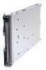
Removing the system board assembly When replacing the system board, you will replace the system board and blade base as one assembly. After replacement, you must either update the blade workstation with the latest firmware or restore the pre-existing firmware that the customer provides on a diskette or CD image. Note: See "System board layouts" on page 7 for more information on the locations of the connectors, jumpers and LEDs on the system board. To remove the system board assembly, complete the following steps: 1. Read the safety information that begins on page vii, and "Installation guidelines" on page 13. 2. If the blade workstation is installed in a BladeCenter unit, remove it (see "Removing the blade workstation from a BladeCenter unit" on page 16 for instructions). 3. Remove the blade workstation cover (see "Removing the blade workstation cover" on page 19). 4. Remove the blade workstation bezel assembly (see "Removing the bezel assembly" on page 21). 5. Remove all of the installed components in the following list from the system board assembly; then, place them on a non-conductive surface or install them on the new system board assembly. v Compression card. See "Removing a compression card" on page 26. v Graphics card. See "Removing a graphics card" on page 28. v DIMMs. See "Removing a memory module" on page 24. v Hard disk drive. See "Removing a SATA storage drive" on page 22. v Microprocessor and heat sink. See "Removing a microprocessor and heat sink" on page 32. 6. If you are instructed to return the system board assembly, follow all packaging instructions, and use any packaging materials for shipping that are supplied to you. 36 BladeCenter HC10 Type 7996: Problem Determination and Service Guide
-
 1
1 -
2
-
3
-
4
-
5
-
6
-
7
-
8
-
9
-
10
-
11
-
12
-
13
-
14
-
15
-
16
-
17
-
18
-
19
-
20
-
21
-
22
-
23
-
24
-
25
-
26
-
27
-
28
-
29
-
30
-
31
-
32
-
33
-
34
-
35
-
36
-
37
-
38
-
39
-
40
-
41
-
42
-
43
-
44
-
45
-
46
-
 47
47 -
 48
48 -
 49
49 -
 50
50 -
 51
51 -
 52
52 -
 53
53 -
 54
54 -
 55
55 -
 56
56 -
 57
57 -
58
-
59
-
60
-
61
-
62
-
63
-
64
-
65
-
66
-
67
-
68
-
69
-
70
-
71
-
72
-
73
-
74
-
75
-
76
-
77
-
78
-
79
-
80
-
81
-
82
-
83
-
84
-
85
-
86
-
87
-
88
-
89
-
90
-
91
-
92
-
93
-
94
-
95
-
96
-
97
-
98
-
99
-
100
-
101
-
102
-
103
-
104
-
105
-
106
-
107
-
108
-
109
-
110
-
111
-
112
-
113
-
114
 |
 |
