Kyocera 9530DN Operation Guide - Page 156
Serial Interface (Option), Interface Signals, Interface voltage levels
 |
View all Kyocera 9530DN manuals
Add to My Manuals
Save this manual to your list of manuals |
Page 156 highlights
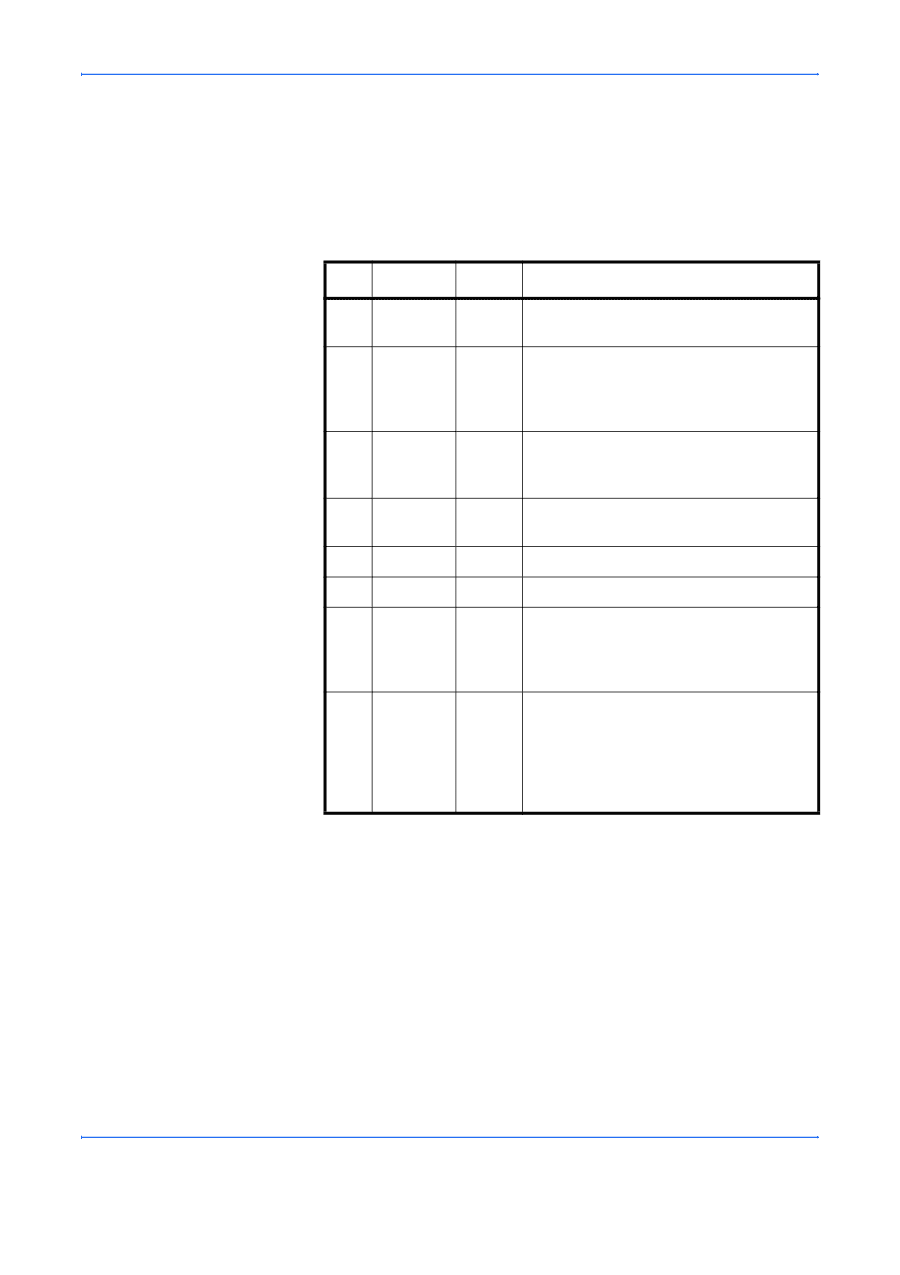
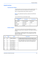
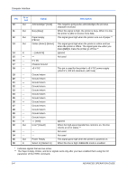
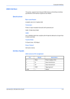
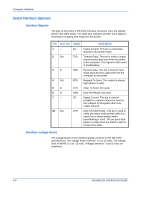
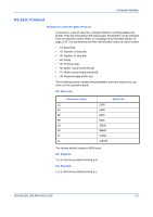
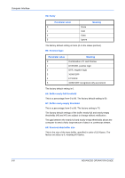
Computer Interface Serial Interface (Option) Interface Signals The pins of the printer's RS-232C interface connector carry the signals listed in the table below. The table also indicates whether each signal is incoming or outgoing with respect to the printer. Pin In or out Signal Description 1- 2 Out 3 In 4 Out 5 In 6 In 7- 20 Out FG TXD RXD RTS CTS DSR SG DTR Frame Ground. This pin is connected directly to the printer frame. Transmit Data. This pin is used to output asynchronous data sent from the printer to the computer. This signal is often used in handshaking. Receive Data. This pin is used to input serial asynchronous data sent from the computer to the printer. Request To Send. This output is always high (above 3 volts). Clear To Send. Not used. Data Set Ready. Not used. Signal Ground. This pin is used to establish a common reference level for the voltages of all signals other than Frame Ground. Data Terminal Ready. This pin is used to notify the status of the printer buffer (i.e., nearly full or nearly empty) when handshaking is used. The pin goes high (above 3 volts) when the buffer is able to accept more data. Interface voltage levels The voltage levels of the interface signals conform to EIA RS-232C specifications. The voltage level of SPACE is 3 to 15 volts. The voltage level of MARK is -3 to -15 volts. Voltages between -3 and 3 volts are undefined. 5-6 ADVANCED OPERATION GUIDE
-
 1
1 -
2
-
3
-
4
-
5
-
6
-
7
-
8
-
9
-
10
-
11
-
12
-
13
-
14
-
15
-
16
-
17
-
18
-
19
-
20
-
21
-
22
-
23
-
24
-
25
-
26
-
27
-
28
-
29
-
30
-
31
-
32
-
33
-
34
-
35
-
36
-
37
-
38
-
39
-
40
-
41
-
42
-
43
-
44
-
45
-
46
-
47
-
48
-
49
-
50
-
51
-
52
-
53
-
54
-
55
-
56
-
57
-
58
-
59
-
60
-
61
-
62
-
63
-
64
-
65
-
66
-
67
-
68
-
69
-
70
-
71
-
72
-
73
-
74
-
75
-
76
-
77
-
78
-
79
-
80
-
81
-
82
-
83
-
84
-
85
-
86
-
87
-
88
-
89
-
90
-
91
-
92
-
93
-
94
-
95
-
96
-
97
-
98
-
99
-
100
-
101
-
102
-
103
-
104
-
105
-
106
-
107
-
108
-
109
-
110
-
111
-
112
-
113
-
114
-
115
-
116
-
117
-
118
-
119
-
120
-
121
-
122
-
123
-
124
-
125
-
126
-
127
-
128
-
129
-
130
-
131
-
132
-
133
-
134
-
135
-
136
-
137
-
138
-
139
-
140
-
141
-
142
-
143
-
144
-
145
-
146
-
147
-
148
-
149
-
150
-
 151
151 -
 152
152 -
 153
153 -
 154
154 -
 155
155 -
 156
156 -
 157
157 -
 158
158 -
 159
159 -
 160
160 -
 161
161 -
162
-
163
-
164
-
165
-
166
-
167
-
168
-
169
-
170
 |
 |