Lexmark T632 Service Manual - Page 126
Misalignment of sheets to be stapled., Sheets are transported into output tray but not stapled.
 |
View all Lexmark T632 manuals
Add to My Manuals
Save this manual to your list of manuals |
Page 126 highlights
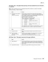
4060-xxx Paper feeds into finisher option output tray-Paper is not stapled-Paper does not align with the right side. FRU 1 Paper alignment wheel Paper alignment pad 2 Paper wheel aligner assembly 3 Stapler board Action Check to make sure the gamma wheel aligner assembly is operating correctly and that the wheel is touching the paper. If the gamma wheel is not turning or touching the paper, go to step 2. If the wheel is turning and touching the paper, check the wheel for wear, damage, or contamination. If any problem with the wheel is found, replace the wheel. Check to make sure the aligner assembly and pads are operating correctly. Make sure the pads are touching the paper and moving the paper to the right side frame. If the aligner pads are not moving into the lower position and touching the paper, go to step 3. If the aligner pads are touching the paper, make sure the pads are not worn, damaged, or contaminated. Replace if necessary. Check the paper wheel aligner assembly to make sure it is mounted correctly. Check to make sure there are no broken gears or other mechanical parts. If any are found, replace the aligner assembly. If no problem is found, go to step 3. Check to make sure the cable to J4 (Accessory) is properly connected to J4 on the board. Turn the printer off, disconnect the motor cable from J4, and check for continuity between J4 pins 1,2,3, and 4 to the motor case. If you get continuity, replace the gearbox drive assembly. If you do not get continuity, continue with the step. Pin No. Voltage static (Motor not running) 1 +24 V dc Voltage feeding (Motor running) +24 V dc 2 +24 V dc Should vary when motor running 3 Not used 4 Ground 5 +5 V dc Should vary when motor running 6 +5 V dc +5 V dc If the voltages are correct, replace the gearbox drive assembly. If the voltages are incorrect, replace the stapler board. Misalignment of sheets to be stapled. FRU 1 Left side bail assembly 2 Stapler gearbox assembly Action Check the left side bail assembly for any signs of binding, missing, or broken parts. Check the stapler gearbox assembly for correct operation. Sheets are transported into output tray but not stapled. FRU 1 Sol 1, stapler drive Stapler assembly Stapler card assembly Action Disconnect Sol 1 cable from J5 on the stapler card and measure the resistance of the solenoid across the cable connector. It should measure approximately 48 ohms (when cold). If incorrect, replace the stapler/finisher option assembly. If correct, replace the stapler card assembly. 2-92 Service Manual
-
 1
1 -
2
-
3
-
4
-
5
-
6
-
7
-
8
-
9
-
10
-
11
-
12
-
13
-
14
-
15
-
16
-
17
-
18
-
19
-
20
-
21
-
22
-
23
-
24
-
25
-
26
-
27
-
28
-
29
-
30
-
31
-
32
-
33
-
34
-
35
-
36
-
37
-
38
-
39
-
40
-
41
-
42
-
43
-
44
-
45
-
46
-
47
-
48
-
49
-
50
-
51
-
52
-
53
-
54
-
55
-
56
-
57
-
58
-
59
-
60
-
61
-
62
-
63
-
64
-
65
-
66
-
67
-
68
-
69
-
70
-
71
-
72
-
73
-
74
-
75
-
76
-
77
-
78
-
79
-
80
-
81
-
82
-
83
-
84
-
85
-
86
-
87
-
88
-
89
-
90
-
91
-
92
-
93
-
94
-
95
-
96
-
97
-
98
-
99
-
100
-
101
-
102
-
103
-
104
-
105
-
106
-
107
-
108
-
109
-
110
-
111
-
112
-
113
-
114
-
115
-
116
-
117
-
118
-
119
-
120
-
 121
121 -
 122
122 -
 123
123 -
 124
124 -
 125
125 -
 126
126 -
 127
127 -
 128
128 -
 129
129 -
 130
130 -
 131
131 -
132
-
133
-
134
-
135
-
136
-
137
-
138
-
139
-
140
-
141
-
142
-
143
-
144
-
145
-
146
-
147
-
148
-
149
-
150
-
151
-
152
-
153
-
154
-
155
-
156
-
157
-
158
-
159
-
160
-
161
-
162
-
163
-
164
-
165
-
166
-
167
-
168
-
169
-
170
-
171
-
172
-
173
-
174
-
175
-
176
-
177
-
178
-
179
-
180
-
181
-
182
-
183
-
184
-
185
-
186
-
187
-
188
-
189
-
190
-
191
-
192
-
193
-
194
-
195
-
196
-
197
-
198
-
199
-
200
-
201
-
202
-
203
-
204
-
205
-
206
-
207
-
208
-
209
-
210
-
211
-
212
-
213
-
214
-
215
-
216
-
217
-
218
-
219
-
220
-
221
-
222
-
223
-
224
-
225
-
226
-
227
-
228
-
229
-
230
-
231
-
232
-
233
-
234
-
235
-
236
-
237
-
238
-
239
-
240
-
241
-
242
-
243
-
244
-
245
-
246
-
247
-
248
-
249
-
250
-
251
-
252
-
253
-
254
-
255
-
256
-
257
-
258
-
259
-
260
-
261
-
262
-
263
-
264
-
265
-
266
-
267
-
268
-
269
-
270
-
271
-
272
-
273
-
274
-
275
-
276
-
277
-
278
-
279
-
280
-
281
-
282
-
283
-
284
-
285
-
286
-
287
-
288
-
289
-
290
-
291
-
292
-
293
-
294
-
295
-
296
-
297
-
298
-
299
-
300
-
301
-
302
-
303
-
304
-
305
-
306
-
307
-
308
-
309
-
310
-
311
-
312
-
313
-
314
-
315
-
316
-
317
-
318
-
319
-
320
-
321
-
322
-
323
-
324
-
325
-
326
-
327
-
328
-
329
-
330
-
331
-
332
-
333
-
334
-
335
-
336
-
337
-
338
-
339
-
340
-
341
-
342
-
343
-
344
-
345
 |
 |
