Lexmark T632 Service Manual - Page 88
Hot fuser service check, CAUTION
 |
View all Lexmark T632 manuals
Add to My Manuals
Save this manual to your list of manuals |
Page 88 highlights
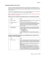
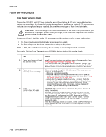
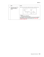
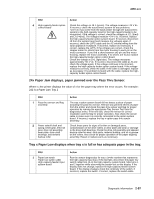
4060-xxx Hot fuser service check Error Code 923: Indicates the fuser is too hot during printing or when the printer is idle. Error code 924: Indicates an open circuit has been detected in the fuser thermistor circuit. Note: Check the fuser sub error codes to help diagnose between a 923 and 924 error. CAUTION: The fuser may be hot, use caution before removing or servicing. CAUTION: There is a danger from hazardous voltage in the area of the printer where you are working. Unplug the printer before you begin, or use caution if the printer must receive power in order to perform the task. FRU 1 Fuser cover assembly (assembly includes thermistor and thermal fuses) 2 Fuser assembly 3 Fuser to system board DC cable 4 System board 5 Fuser hot roll Fuser hot roll bearings Fuser backup roll bearings Fuser backup roll Fuser mechanical parts Action Check for damage to the thermistor assembly. If damage is found, replace the fuser top cover assembly. If no damage is found, check the resistance of the thermistor between pins J6-1 and J6-2 on the cable. • HOT < 10K ohms • COLD = approximately 450K ohms If the resistance is incorrect, replace the fuser top cover assembly. If the resistance is correct, check each pin of J6 to ground. If there is continuity, replace the fuser cover assembly. See "Fuser cover removal" on page 4-25. Check for continuity between J6-1 and J1-2 and between J6-2 and J1-3. If incorrect, replace the fuser assembly. If correct, go to step 3. Check the continuity of the cable. If incorrect, replace the cable. If correct, go to step 4. Measure the voltage on J14-3 on the system board. The voltage should change from approximately +2.5 V dc with the thermistor cold to approximately +1.6 V dc when the thermistor is hot. If incorrect, replace the system board. If correct, go to step 5. Examine the fuser assembly for signs of overheating or damage. Check the hot roll and backup roll for signs of excessive toner, label glue, labels, or other contaminants. If problems are found, replace the fuser assembly. 2-54 Service Manual
-
 1
1 -
2
-
3
-
4
-
5
-
6
-
7
-
8
-
9
-
10
-
11
-
12
-
13
-
14
-
15
-
16
-
17
-
18
-
19
-
20
-
21
-
22
-
23
-
24
-
25
-
26
-
27
-
28
-
29
-
30
-
31
-
32
-
33
-
34
-
35
-
36
-
37
-
38
-
39
-
40
-
41
-
42
-
43
-
44
-
45
-
46
-
47
-
48
-
49
-
50
-
51
-
52
-
53
-
54
-
55
-
56
-
57
-
58
-
59
-
60
-
61
-
62
-
63
-
64
-
65
-
66
-
67
-
68
-
69
-
70
-
71
-
72
-
73
-
74
-
75
-
76
-
77
-
78
-
79
-
80
-
81
-
82
-
 83
83 -
 84
84 -
 85
85 -
 86
86 -
 87
87 -
 88
88 -
 89
89 -
 90
90 -
 91
91 -
 92
92 -
 93
93 -
94
-
95
-
96
-
97
-
98
-
99
-
100
-
101
-
102
-
103
-
104
-
105
-
106
-
107
-
108
-
109
-
110
-
111
-
112
-
113
-
114
-
115
-
116
-
117
-
118
-
119
-
120
-
121
-
122
-
123
-
124
-
125
-
126
-
127
-
128
-
129
-
130
-
131
-
132
-
133
-
134
-
135
-
136
-
137
-
138
-
139
-
140
-
141
-
142
-
143
-
144
-
145
-
146
-
147
-
148
-
149
-
150
-
151
-
152
-
153
-
154
-
155
-
156
-
157
-
158
-
159
-
160
-
161
-
162
-
163
-
164
-
165
-
166
-
167
-
168
-
169
-
170
-
171
-
172
-
173
-
174
-
175
-
176
-
177
-
178
-
179
-
180
-
181
-
182
-
183
-
184
-
185
-
186
-
187
-
188
-
189
-
190
-
191
-
192
-
193
-
194
-
195
-
196
-
197
-
198
-
199
-
200
-
201
-
202
-
203
-
204
-
205
-
206
-
207
-
208
-
209
-
210
-
211
-
212
-
213
-
214
-
215
-
216
-
217
-
218
-
219
-
220
-
221
-
222
-
223
-
224
-
225
-
226
-
227
-
228
-
229
-
230
-
231
-
232
-
233
-
234
-
235
-
236
-
237
-
238
-
239
-
240
-
241
-
242
-
243
-
244
-
245
-
246
-
247
-
248
-
249
-
250
-
251
-
252
-
253
-
254
-
255
-
256
-
257
-
258
-
259
-
260
-
261
-
262
-
263
-
264
-
265
-
266
-
267
-
268
-
269
-
270
-
271
-
272
-
273
-
274
-
275
-
276
-
277
-
278
-
279
-
280
-
281
-
282
-
283
-
284
-
285
-
286
-
287
-
288
-
289
-
290
-
291
-
292
-
293
-
294
-
295
-
296
-
297
-
298
-
299
-
300
-
301
-
302
-
303
-
304
-
305
-
306
-
307
-
308
-
309
-
310
-
311
-
312
-
313
-
314
-
315
-
316
-
317
-
318
-
319
-
320
-
321
-
322
-
323
-
324
-
325
-
326
-
327
-
328
-
329
-
330
-
331
-
332
-
333
-
334
-
335
-
336
-
337
-
338
-
339
-
340
-
341
-
342
-
343
-
344
-
345
 |
 |
