Lexmark T632 Service Manual - Page 188
Inner shield removal, Input sensor removal
 |
View all Lexmark T632 manuals
Add to My Manuals
Save this manual to your list of manuals |
Page 188 highlights
4060-xxx Inner shield removal 1. Remove the left door. 2. Remove the outer system board shield. See"Outer shield removal" on page 4-52. 3. Remove all features or option boards from the interconnect board. Warning: Observe all ESD precautions while handling ESD-sensitive parts. See "Handling ESD-sensitive parts" on page 4-1. 4. Disconnect all cables from the system board. 5. Remove the inner shield mounting screws (A). 6. Remove the USB connector mounting screw (B), if present. 7. Remove the inner shield. B A A Input sensor removal 1. Remove the inner paper deflector assembly. 2. Disconnect the input sensor cable from the input sensor. 3. Release the input sensor from its mounting and remove. 4-34 Service Manual
-
 1
1 -
2
-
3
-
4
-
5
-
6
-
7
-
8
-
9
-
10
-
11
-
12
-
13
-
14
-
15
-
16
-
17
-
18
-
19
-
20
-
21
-
22
-
23
-
24
-
25
-
26
-
27
-
28
-
29
-
30
-
31
-
32
-
33
-
34
-
35
-
36
-
37
-
38
-
39
-
40
-
41
-
42
-
43
-
44
-
45
-
46
-
47
-
48
-
49
-
50
-
51
-
52
-
53
-
54
-
55
-
56
-
57
-
58
-
59
-
60
-
61
-
62
-
63
-
64
-
65
-
66
-
67
-
68
-
69
-
70
-
71
-
72
-
73
-
74
-
75
-
76
-
77
-
78
-
79
-
80
-
81
-
82
-
83
-
84
-
85
-
86
-
87
-
88
-
89
-
90
-
91
-
92
-
93
-
94
-
95
-
96
-
97
-
98
-
99
-
100
-
101
-
102
-
103
-
104
-
105
-
106
-
107
-
108
-
109
-
110
-
111
-
112
-
113
-
114
-
115
-
116
-
117
-
118
-
119
-
120
-
121
-
122
-
123
-
124
-
125
-
126
-
127
-
128
-
129
-
130
-
131
-
132
-
133
-
134
-
135
-
136
-
137
-
138
-
139
-
140
-
141
-
142
-
143
-
144
-
145
-
146
-
147
-
148
-
149
-
150
-
151
-
152
-
153
-
154
-
155
-
156
-
157
-
158
-
159
-
160
-
161
-
162
-
163
-
164
-
165
-
166
-
167
-
168
-
169
-
170
-
171
-
172
-
173
-
174
-
175
-
176
-
177
-
178
-
179
-
180
-
181
-
182
-
 183
183 -
 184
184 -
 185
185 -
 186
186 -
 187
187 -
 188
188 -
 189
189 -
 190
190 -
 191
191 -
 192
192 -
 193
193 -
194
-
195
-
196
-
197
-
198
-
199
-
200
-
201
-
202
-
203
-
204
-
205
-
206
-
207
-
208
-
209
-
210
-
211
-
212
-
213
-
214
-
215
-
216
-
217
-
218
-
219
-
220
-
221
-
222
-
223
-
224
-
225
-
226
-
227
-
228
-
229
-
230
-
231
-
232
-
233
-
234
-
235
-
236
-
237
-
238
-
239
-
240
-
241
-
242
-
243
-
244
-
245
-
246
-
247
-
248
-
249
-
250
-
251
-
252
-
253
-
254
-
255
-
256
-
257
-
258
-
259
-
260
-
261
-
262
-
263
-
264
-
265
-
266
-
267
-
268
-
269
-
270
-
271
-
272
-
273
-
274
-
275
-
276
-
277
-
278
-
279
-
280
-
281
-
282
-
283
-
284
-
285
-
286
-
287
-
288
-
289
-
290
-
291
-
292
-
293
-
294
-
295
-
296
-
297
-
298
-
299
-
300
-
301
-
302
-
303
-
304
-
305
-
306
-
307
-
308
-
309
-
310
-
311
-
312
-
313
-
314
-
315
-
316
-
317
-
318
-
319
-
320
-
321
-
322
-
323
-
324
-
325
-
326
-
327
-
328
-
329
-
330
-
331
-
332
-
333
-
334
-
335
-
336
-
337
-
338
-
339
-
340
-
341
-
342
-
343
-
344
-
345
 |
 |

4-34
Service Manual
4060-
xxx
Inner shield removal
1.
Remove the left door.
2.
Remove the outer system board shield. See
“Outer shield removal” on page 4-52
.
3.
Remove all features or option boards from the interconnect board.
Warning:
Observe all ESD precautions while handling ESD-sensitive parts. See
“Handling
ESD-sensitive parts” on page 4-1
.
4.
Disconnect all cables from the system board.
5.
Remove the inner shield mounting screws (A).
6.
Remove the USB connector mounting screw (B), if present.
7.
Remove the inner shield.
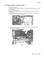
Input sensor removal
1.
Remove the inner paper deflector assembly.
2.
Disconnect the input sensor cable from the input sensor.
3.
Release the input sensor from its mounting and remove.
A
A
B