Lexmark T632 Service Manual - Page 74
is full-message that Bin, Full displays and paper feeds into bin
 |
View all Lexmark T632 manuals
Add to My Manuals
Save this manual to your list of manuals |
Page 74 highlights
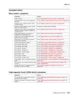
4060-xxx Ready Bin x Full displays-May be able to clear message and feed paper into bin selected. FRU 1 Bin x sensor Bin x sensor cable Bin x sensor flag Control board Action Check the sensor and sensor cable for the bin that is displaying the message to make sure the sensor is seated correctly in the side of the tray and the cable is connected to the sensor and the control board. Check the flag for binding and proper operation. If correct, replace the bin x sensor. If this does not fix the problem, replace the control board. Note: This sensor is in a normally open position with the flag out of the sensor slot. Bin x is full-message that Bin x is Full does not display. FRU 1 Bin x sensor Bin x sensor cable Bin x sensor flag Bin x sensor flag Control board Action Check the sensor flag for binds, broken or missing parts. If correct, check the bin sensor for correct installation in the side of the tray. If the bin sensor is installed correctly, check the sensor cable for correct installation to the sensor and control board. If correct, replace the bin x sensor. If this does not fix the problem, replace the control board. Ready-Bin x Full displays and paper feeds into bin x. FRU 1 Bin x sensor Bin x sensor control board Action Check the sensor flag for binds. Make sure the sensor flag is not in an up position. If the sensor flag is operating correctly, replace the bin x sensor. If this does not fix the problem, replace the control board. 271 Paper Jam - Check Bin 1 displays-paper does not feed into the bin selected FRU 1 Deflector Deflector spring Deflector cover Deflector cover spring Shaft assemblies 2 Bin x solenoid assembly Control board 3 Mechanical linkage Motor assembly Action Check all the bin parts for missing or loose springs, binds in the deflector or deflector cover, broken or binding shaft assemblies, or broken gear teeth. If incorrect, repair as necessary. Check the solenoid for any binds. Make sure the solenoid is contacting the latch correctly. If incorrect, repair as necessary. If the solenoid appears to be operating mechanically, check the resistance of the solenoid. It measures between 30 and 50 ohms. If incorrect, replace the failing solenoid assembly. If correct, replace the control board. If the DC motor is functioning properly, check the gears, clutch, and other linkage parts for correct operation and wear, broken gear teeth, or damaged parts. If incorrect, replace the mechanical linkage assembly/DC motor assembly. 2-40 Service Manual
-
 1
1 -
2
-
3
-
4
-
5
-
6
-
7
-
8
-
9
-
10
-
11
-
12
-
13
-
14
-
15
-
16
-
17
-
18
-
19
-
20
-
21
-
22
-
23
-
24
-
25
-
26
-
27
-
28
-
29
-
30
-
31
-
32
-
33
-
34
-
35
-
36
-
37
-
38
-
39
-
40
-
41
-
42
-
43
-
44
-
45
-
46
-
47
-
48
-
49
-
50
-
51
-
52
-
53
-
54
-
55
-
56
-
57
-
58
-
59
-
60
-
61
-
62
-
63
-
64
-
65
-
66
-
67
-
68
-
 69
69 -
 70
70 -
 71
71 -
 72
72 -
 73
73 -
 74
74 -
 75
75 -
 76
76 -
 77
77 -
 78
78 -
 79
79 -
80
-
81
-
82
-
83
-
84
-
85
-
86
-
87
-
88
-
89
-
90
-
91
-
92
-
93
-
94
-
95
-
96
-
97
-
98
-
99
-
100
-
101
-
102
-
103
-
104
-
105
-
106
-
107
-
108
-
109
-
110
-
111
-
112
-
113
-
114
-
115
-
116
-
117
-
118
-
119
-
120
-
121
-
122
-
123
-
124
-
125
-
126
-
127
-
128
-
129
-
130
-
131
-
132
-
133
-
134
-
135
-
136
-
137
-
138
-
139
-
140
-
141
-
142
-
143
-
144
-
145
-
146
-
147
-
148
-
149
-
150
-
151
-
152
-
153
-
154
-
155
-
156
-
157
-
158
-
159
-
160
-
161
-
162
-
163
-
164
-
165
-
166
-
167
-
168
-
169
-
170
-
171
-
172
-
173
-
174
-
175
-
176
-
177
-
178
-
179
-
180
-
181
-
182
-
183
-
184
-
185
-
186
-
187
-
188
-
189
-
190
-
191
-
192
-
193
-
194
-
195
-
196
-
197
-
198
-
199
-
200
-
201
-
202
-
203
-
204
-
205
-
206
-
207
-
208
-
209
-
210
-
211
-
212
-
213
-
214
-
215
-
216
-
217
-
218
-
219
-
220
-
221
-
222
-
223
-
224
-
225
-
226
-
227
-
228
-
229
-
230
-
231
-
232
-
233
-
234
-
235
-
236
-
237
-
238
-
239
-
240
-
241
-
242
-
243
-
244
-
245
-
246
-
247
-
248
-
249
-
250
-
251
-
252
-
253
-
254
-
255
-
256
-
257
-
258
-
259
-
260
-
261
-
262
-
263
-
264
-
265
-
266
-
267
-
268
-
269
-
270
-
271
-
272
-
273
-
274
-
275
-
276
-
277
-
278
-
279
-
280
-
281
-
282
-
283
-
284
-
285
-
286
-
287
-
288
-
289
-
290
-
291
-
292
-
293
-
294
-
295
-
296
-
297
-
298
-
299
-
300
-
301
-
302
-
303
-
304
-
305
-
306
-
307
-
308
-
309
-
310
-
311
-
312
-
313
-
314
-
315
-
316
-
317
-
318
-
319
-
320
-
321
-
322
-
323
-
324
-
325
-
326
-
327
-
328
-
329
-
330
-
331
-
332
-
333
-
334
-
335
-
336
-
337
-
338
-
339
-
340
-
341
-
342
-
343
-
344
-
345
 |
 |
