Lexmark T632 Service Manual - Page 171
Installation
 |
View all Lexmark T632 manuals
Add to My Manuals
Save this manual to your list of manuals |
Page 171 highlights
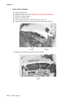
4060-xxx Installation 1. Remove any washer that may be present (A) and discard. 2. Lubricate areas (A) that engage the journal (B) with grease, from the provided packet. 3. Place the new washer (C) on the bevel gear shaft. 4. Insert the bottom portion and press or pull into position. Note: You should hear two distinct snaps. If you only hear one, the bevel gear is only partially engaged and you should continue to press until the second snap is heard. Very firm pressure is required. CAUTION: Do not brace your hands below the bevel gear itself. When the gear double-snaps into place, it may pinch your hand. 5. Install the power takeoff shaft and spring. 6. Install the gear guard. 7. Install the inner shield. Repair information 4-17
-
 1
1 -
2
-
3
-
4
-
5
-
6
-
7
-
8
-
9
-
10
-
11
-
12
-
13
-
14
-
15
-
16
-
17
-
18
-
19
-
20
-
21
-
22
-
23
-
24
-
25
-
26
-
27
-
28
-
29
-
30
-
31
-
32
-
33
-
34
-
35
-
36
-
37
-
38
-
39
-
40
-
41
-
42
-
43
-
44
-
45
-
46
-
47
-
48
-
49
-
50
-
51
-
52
-
53
-
54
-
55
-
56
-
57
-
58
-
59
-
60
-
61
-
62
-
63
-
64
-
65
-
66
-
67
-
68
-
69
-
70
-
71
-
72
-
73
-
74
-
75
-
76
-
77
-
78
-
79
-
80
-
81
-
82
-
83
-
84
-
85
-
86
-
87
-
88
-
89
-
90
-
91
-
92
-
93
-
94
-
95
-
96
-
97
-
98
-
99
-
100
-
101
-
102
-
103
-
104
-
105
-
106
-
107
-
108
-
109
-
110
-
111
-
112
-
113
-
114
-
115
-
116
-
117
-
118
-
119
-
120
-
121
-
122
-
123
-
124
-
125
-
126
-
127
-
128
-
129
-
130
-
131
-
132
-
133
-
134
-
135
-
136
-
137
-
138
-
139
-
140
-
141
-
142
-
143
-
144
-
145
-
146
-
147
-
148
-
149
-
150
-
151
-
152
-
153
-
154
-
155
-
156
-
157
-
158
-
159
-
160
-
161
-
162
-
163
-
164
-
165
-
 166
166 -
 167
167 -
 168
168 -
 169
169 -
 170
170 -
 171
171 -
 172
172 -
 173
173 -
 174
174 -
 175
175 -
 176
176 -
177
-
178
-
179
-
180
-
181
-
182
-
183
-
184
-
185
-
186
-
187
-
188
-
189
-
190
-
191
-
192
-
193
-
194
-
195
-
196
-
197
-
198
-
199
-
200
-
201
-
202
-
203
-
204
-
205
-
206
-
207
-
208
-
209
-
210
-
211
-
212
-
213
-
214
-
215
-
216
-
217
-
218
-
219
-
220
-
221
-
222
-
223
-
224
-
225
-
226
-
227
-
228
-
229
-
230
-
231
-
232
-
233
-
234
-
235
-
236
-
237
-
238
-
239
-
240
-
241
-
242
-
243
-
244
-
245
-
246
-
247
-
248
-
249
-
250
-
251
-
252
-
253
-
254
-
255
-
256
-
257
-
258
-
259
-
260
-
261
-
262
-
263
-
264
-
265
-
266
-
267
-
268
-
269
-
270
-
271
-
272
-
273
-
274
-
275
-
276
-
277
-
278
-
279
-
280
-
281
-
282
-
283
-
284
-
285
-
286
-
287
-
288
-
289
-
290
-
291
-
292
-
293
-
294
-
295
-
296
-
297
-
298
-
299
-
300
-
301
-
302
-
303
-
304
-
305
-
306
-
307
-
308
-
309
-
310
-
311
-
312
-
313
-
314
-
315
-
316
-
317
-
318
-
319
-
320
-
321
-
322
-
323
-
324
-
325
-
326
-
327
-
328
-
329
-
330
-
331
-
332
-
333
-
334
-
335
-
336
-
337
-
338
-
339
-
340
-
341
-
342
-
343
-
344
-
345
 |
 |

Repair information
4-17
4060-
xxx
Installation
1.
Remove any washer that may be present (A) and discard.
2.
Lubricate areas (A) that engage the journal (B) with grease, from the provided packet.
3.
Place the new washer (C) on the bevel gear shaft.
4.
Insert the bottom portion and press or pull into position.
Note:
You should hear two distinct
snaps
. If you only hear one, the bevel gear is only partially
engaged and you should continue to press until the second
snap
is heard. Very firm pressure is
required.
CAUTION:
Do not brace your hands below the bevel gear itself. When the gear double-
snaps
into place, it may pinch your hand.
5.
Install the power takeoff shaft and spring.
6.
Install the gear guard.
7.
Install the inner shield.