Lexmark T632 Service Manual - Page 92
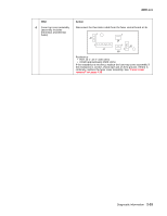
The elevator tray fails to stop at the correct position and continues to drive, into the bottom frame.
 |
View all Lexmark T632 manuals
Add to My Manuals
Save this manual to your list of manuals |
Page 92 highlights
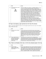
4060-xxx Tray x empty displays when there is paper in the high-capacity feeder input tray. FRU 1 Paper out sensor flag 2 Paper out sensor (on option system board) Action Check the paper out sensor flag for correct operation and installation. If correct, replace the high-capacity feeder system board. (The paper out sensor is mounted on the high-capacity feeder system board.) The elevator tray fails to stop at the correct position and continues to drive into the bottom frame. FRU 1 Lower limit switch Lower limit switch cable 2 High-capacity feeder control board Action Check continuity of the lower limit switch. If incorrect, replace the switch. If correct, check the switch cable. If incorrect, replace the cable. If correct, replace the high-capacity feeder option control board. Disconnect the lower limit switch cable and check the voltage at J2-1 (orange). The voltage measures approximately +5 V dc. If incorrect, replace the high-capacity feeder option control board. The elevator tray down button does not operate. The tray moves to the upper position. Service tip: Open the high-capacity feeder front door and check the black rubber bumper attached to the door switch spring. Be sure the rubber button is centered and not touching the sides of the hole or the switch will not function properly. FRU 1 Lower limit switch Lower limit switch cable High-capacity feeder control board Action Check the lower limit switch to make sure it is not closed (normally open). If incorrect, replace the switch. Check the lower limit switch cable for a short between pins 1 and 2. If incorrect, replace the cable. If correct, replace the high-capacity feeder control board. Paper from the high-capacity feeder input tray does not reach the pass thru sensor. Service tip: Be sure the paper in tray is within specifications. FRU 1 Autocompensator assembly 2 Wear strips Action Check the autocompensator pick arm rollers for sign of glazing, toner or other buildup. Replace as necessary. Check the wear strips for glazing or contamination. Replace as required. It is advisable to replace all four wear strips at the same time. 2-58 Service Manual
-
 1
1 -
2
-
3
-
4
-
5
-
6
-
7
-
8
-
9
-
10
-
11
-
12
-
13
-
14
-
15
-
16
-
17
-
18
-
19
-
20
-
21
-
22
-
23
-
24
-
25
-
26
-
27
-
28
-
29
-
30
-
31
-
32
-
33
-
34
-
35
-
36
-
37
-
38
-
39
-
40
-
41
-
42
-
43
-
44
-
45
-
46
-
47
-
48
-
49
-
50
-
51
-
52
-
53
-
54
-
55
-
56
-
57
-
58
-
59
-
60
-
61
-
62
-
63
-
64
-
65
-
66
-
67
-
68
-
69
-
70
-
71
-
72
-
73
-
74
-
75
-
76
-
77
-
78
-
79
-
80
-
81
-
82
-
83
-
84
-
85
-
86
-
 87
87 -
 88
88 -
 89
89 -
 90
90 -
 91
91 -
 92
92 -
 93
93 -
 94
94 -
 95
95 -
 96
96 -
 97
97 -
98
-
99
-
100
-
101
-
102
-
103
-
104
-
105
-
106
-
107
-
108
-
109
-
110
-
111
-
112
-
113
-
114
-
115
-
116
-
117
-
118
-
119
-
120
-
121
-
122
-
123
-
124
-
125
-
126
-
127
-
128
-
129
-
130
-
131
-
132
-
133
-
134
-
135
-
136
-
137
-
138
-
139
-
140
-
141
-
142
-
143
-
144
-
145
-
146
-
147
-
148
-
149
-
150
-
151
-
152
-
153
-
154
-
155
-
156
-
157
-
158
-
159
-
160
-
161
-
162
-
163
-
164
-
165
-
166
-
167
-
168
-
169
-
170
-
171
-
172
-
173
-
174
-
175
-
176
-
177
-
178
-
179
-
180
-
181
-
182
-
183
-
184
-
185
-
186
-
187
-
188
-
189
-
190
-
191
-
192
-
193
-
194
-
195
-
196
-
197
-
198
-
199
-
200
-
201
-
202
-
203
-
204
-
205
-
206
-
207
-
208
-
209
-
210
-
211
-
212
-
213
-
214
-
215
-
216
-
217
-
218
-
219
-
220
-
221
-
222
-
223
-
224
-
225
-
226
-
227
-
228
-
229
-
230
-
231
-
232
-
233
-
234
-
235
-
236
-
237
-
238
-
239
-
240
-
241
-
242
-
243
-
244
-
245
-
246
-
247
-
248
-
249
-
250
-
251
-
252
-
253
-
254
-
255
-
256
-
257
-
258
-
259
-
260
-
261
-
262
-
263
-
264
-
265
-
266
-
267
-
268
-
269
-
270
-
271
-
272
-
273
-
274
-
275
-
276
-
277
-
278
-
279
-
280
-
281
-
282
-
283
-
284
-
285
-
286
-
287
-
288
-
289
-
290
-
291
-
292
-
293
-
294
-
295
-
296
-
297
-
298
-
299
-
300
-
301
-
302
-
303
-
304
-
305
-
306
-
307
-
308
-
309
-
310
-
311
-
312
-
313
-
314
-
315
-
316
-
317
-
318
-
319
-
320
-
321
-
322
-
323
-
324
-
325
-
326
-
327
-
328
-
329
-
330
-
331
-
332
-
333
-
334
-
335
-
336
-
337
-
338
-
339
-
340
-
341
-
342
-
343
-
344
-
345
 |
 |
