Lexmark T632 Service Manual - Page 128
Transfer roll service check - 80 scheduled maintenance
 |
View all Lexmark T632 manuals
Add to My Manuals
Save this manual to your list of manuals |
Page 128 highlights
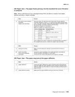
4060-xxx Transfer roll service check Service tip: The transfer roll is 51.02 mm (2.009 inch) circumference. Any print quality problems such as lines that are spaced 51.02 mm apart indicate you should check the transfer roll for damage and check for toner or foreign material buildup. Service tip: The transfer roll assembly is part of the maintenance kit and is replaced when an 80 Scheduled Maintenance displays. Ask the customer if they have replaced the transfer roll recently. CAUTION: Make sure the printer is unplugged before making any checks on the transfer roll or associated parts for personal safety and to prevent damage to the printer. FRU 1 Transfer roll assembly 2 Left transfer arm assembly 3 Right transfer arm assembly 4 HVPS-917 Error code Action Check the transfer roll for toner buildup, surface damage to the roll, oil, or other contaminants on the surface of the roll. Replace the transfer roll as necessary. Check the left transfer roll arm assembly to make sure it is fastened and locked in the down position. If the arm is not locked down, make sure the arm is not broken and locks into the EP frame correctly. Check the left transfer arm assembly spring for proper operation. Check the right transfer arm assembly to make sure it is fastened and locked in the down position. If the arm is not locked down, make sure the arm is not broken and locks into the EP frame correctly. Check the right transfer arm assembly spring for proper operation. For any background problems, ensure the contact to the HVPS board is correct and that there is approximately 0 ohms resistance between the transfer roll shaft and the HVPS contact. If correct, go to "Print quality-background" on page 2-82. Check the voltage at J22-3. The voltage changes from +24 V dc with the printer idle to 0 V dc when the printer runs the print test. If the voltage is incorrect, check the continuity of line J22-3 in the front cable harness to the HVPS. If there is no continuity, replace the cable harness. If there is continuity, replace the HVPS. If the problem continues, replace the system board. 2-94 Service Manual
-
 1
1 -
2
-
3
-
4
-
5
-
6
-
7
-
8
-
9
-
10
-
11
-
12
-
13
-
14
-
15
-
16
-
17
-
18
-
19
-
20
-
21
-
22
-
23
-
24
-
25
-
26
-
27
-
28
-
29
-
30
-
31
-
32
-
33
-
34
-
35
-
36
-
37
-
38
-
39
-
40
-
41
-
42
-
43
-
44
-
45
-
46
-
47
-
48
-
49
-
50
-
51
-
52
-
53
-
54
-
55
-
56
-
57
-
58
-
59
-
60
-
61
-
62
-
63
-
64
-
65
-
66
-
67
-
68
-
69
-
70
-
71
-
72
-
73
-
74
-
75
-
76
-
77
-
78
-
79
-
80
-
81
-
82
-
83
-
84
-
85
-
86
-
87
-
88
-
89
-
90
-
91
-
92
-
93
-
94
-
95
-
96
-
97
-
98
-
99
-
100
-
101
-
102
-
103
-
104
-
105
-
106
-
107
-
108
-
109
-
110
-
111
-
112
-
113
-
114
-
115
-
116
-
117
-
118
-
119
-
120
-
121
-
122
-
 123
123 -
 124
124 -
 125
125 -
 126
126 -
 127
127 -
 128
128 -
 129
129 -
 130
130 -
 131
131 -
 132
132 -
 133
133 -
134
-
135
-
136
-
137
-
138
-
139
-
140
-
141
-
142
-
143
-
144
-
145
-
146
-
147
-
148
-
149
-
150
-
151
-
152
-
153
-
154
-
155
-
156
-
157
-
158
-
159
-
160
-
161
-
162
-
163
-
164
-
165
-
166
-
167
-
168
-
169
-
170
-
171
-
172
-
173
-
174
-
175
-
176
-
177
-
178
-
179
-
180
-
181
-
182
-
183
-
184
-
185
-
186
-
187
-
188
-
189
-
190
-
191
-
192
-
193
-
194
-
195
-
196
-
197
-
198
-
199
-
200
-
201
-
202
-
203
-
204
-
205
-
206
-
207
-
208
-
209
-
210
-
211
-
212
-
213
-
214
-
215
-
216
-
217
-
218
-
219
-
220
-
221
-
222
-
223
-
224
-
225
-
226
-
227
-
228
-
229
-
230
-
231
-
232
-
233
-
234
-
235
-
236
-
237
-
238
-
239
-
240
-
241
-
242
-
243
-
244
-
245
-
246
-
247
-
248
-
249
-
250
-
251
-
252
-
253
-
254
-
255
-
256
-
257
-
258
-
259
-
260
-
261
-
262
-
263
-
264
-
265
-
266
-
267
-
268
-
269
-
270
-
271
-
272
-
273
-
274
-
275
-
276
-
277
-
278
-
279
-
280
-
281
-
282
-
283
-
284
-
285
-
286
-
287
-
288
-
289
-
290
-
291
-
292
-
293
-
294
-
295
-
296
-
297
-
298
-
299
-
300
-
301
-
302
-
303
-
304
-
305
-
306
-
307
-
308
-
309
-
310
-
311
-
312
-
313
-
314
-
315
-
316
-
317
-
318
-
319
-
320
-
321
-
322
-
323
-
324
-
325
-
326
-
327
-
328
-
329
-
330
-
331
-
332
-
333
-
334
-
335
-
336
-
337
-
338
-
339
-
340
-
341
-
342
-
343
-
344
-
345
 |
 |
