Lexmark T632 Service Manual - Page 96
High-capacity output stacker service check, Problems with excessive static electricity buildup.
 |
View all Lexmark T632 manuals
Add to My Manuals
Save this manual to your list of manuals |
Page 96 highlights
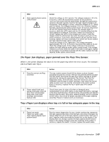
4060-xxx High-capacity output stacker service check Service tip: The majority of the mechanical components can be observed during operation by removing the left, right, and front covers. The high-capacity output stacker option functions without the covers installed. Determine which paper path stacker assembly is not functioning properly. Make sure the option(s) are installed correctly and the machine is configured correctly before attempting to service the high-capacity output stacker option. See "High-capacity output stacker board" on page 5-3 to identify the correct jumper locations at J6 for the upper and lower units. Problems with excessive static electricity buildup. FRU 1 Front Cover Assembly Action Check the front cover assembly to make sure the ESD brush ground lead is firmly attached to the high-capacity option. Also check to make sure the ESD brush is not loose or damaged. The printer does not recognize one or more output options as installed. Service tip: If more than a single output option is installed, check each one to see if the printer recognizes any single option as installed. If the printer recognizes any of the output options, the base printer autoconnect system is operating correctly. The problem is in the unrecognized option. Continue with this service check or go to the service check for the failing output option. FRU 1 High-capacity stacker feeder 2 High-capacity output stacker/mechanical linkage assembly Action Check the autoconnects, cables, and connectors of the option for any signs of loose or damaged parts. Remove the left and right side covers and check all four autoconnects for damage, especially the connector pins. Remove the output option and check the voltages on the standard output bin autoconnect located on the top left rear of the printer. Go to "Autoconnect" on page 5-1. If the voltages are correct, reinstall the output option and note the positions of the toroids on the autoconnect cables on the upper and lower assemblies, and check the voltages on the autoconnects. If all voltages are correct and the lower assembly is failing, replace the lower control board. If the upper assembly is failing, replace the upper control board. If the voltages are incorrect, replace the upper or lower failing mechanical linkage assembly. 2-62 Service Manual
-
 1
1 -
2
-
3
-
4
-
5
-
6
-
7
-
8
-
9
-
10
-
11
-
12
-
13
-
14
-
15
-
16
-
17
-
18
-
19
-
20
-
21
-
22
-
23
-
24
-
25
-
26
-
27
-
28
-
29
-
30
-
31
-
32
-
33
-
34
-
35
-
36
-
37
-
38
-
39
-
40
-
41
-
42
-
43
-
44
-
45
-
46
-
47
-
48
-
49
-
50
-
51
-
52
-
53
-
54
-
55
-
56
-
57
-
58
-
59
-
60
-
61
-
62
-
63
-
64
-
65
-
66
-
67
-
68
-
69
-
70
-
71
-
72
-
73
-
74
-
75
-
76
-
77
-
78
-
79
-
80
-
81
-
82
-
83
-
84
-
85
-
86
-
87
-
88
-
89
-
90
-
 91
91 -
 92
92 -
 93
93 -
 94
94 -
 95
95 -
 96
96 -
 97
97 -
 98
98 -
 99
99 -
 100
100 -
 101
101 -
102
-
103
-
104
-
105
-
106
-
107
-
108
-
109
-
110
-
111
-
112
-
113
-
114
-
115
-
116
-
117
-
118
-
119
-
120
-
121
-
122
-
123
-
124
-
125
-
126
-
127
-
128
-
129
-
130
-
131
-
132
-
133
-
134
-
135
-
136
-
137
-
138
-
139
-
140
-
141
-
142
-
143
-
144
-
145
-
146
-
147
-
148
-
149
-
150
-
151
-
152
-
153
-
154
-
155
-
156
-
157
-
158
-
159
-
160
-
161
-
162
-
163
-
164
-
165
-
166
-
167
-
168
-
169
-
170
-
171
-
172
-
173
-
174
-
175
-
176
-
177
-
178
-
179
-
180
-
181
-
182
-
183
-
184
-
185
-
186
-
187
-
188
-
189
-
190
-
191
-
192
-
193
-
194
-
195
-
196
-
197
-
198
-
199
-
200
-
201
-
202
-
203
-
204
-
205
-
206
-
207
-
208
-
209
-
210
-
211
-
212
-
213
-
214
-
215
-
216
-
217
-
218
-
219
-
220
-
221
-
222
-
223
-
224
-
225
-
226
-
227
-
228
-
229
-
230
-
231
-
232
-
233
-
234
-
235
-
236
-
237
-
238
-
239
-
240
-
241
-
242
-
243
-
244
-
245
-
246
-
247
-
248
-
249
-
250
-
251
-
252
-
253
-
254
-
255
-
256
-
257
-
258
-
259
-
260
-
261
-
262
-
263
-
264
-
265
-
266
-
267
-
268
-
269
-
270
-
271
-
272
-
273
-
274
-
275
-
276
-
277
-
278
-
279
-
280
-
281
-
282
-
283
-
284
-
285
-
286
-
287
-
288
-
289
-
290
-
291
-
292
-
293
-
294
-
295
-
296
-
297
-
298
-
299
-
300
-
301
-
302
-
303
-
304
-
305
-
306
-
307
-
308
-
309
-
310
-
311
-
312
-
313
-
314
-
315
-
316
-
317
-
318
-
319
-
320
-
321
-
322
-
323
-
324
-
325
-
326
-
327
-
328
-
329
-
330
-
331
-
332
-
333
-
334
-
335
-
336
-
337
-
338
-
339
-
340
-
341
-
342
-
343
-
344
-
345
 |
 |
