Lexmark T632 Service Manual - Page 84
Operator panel displays 260 Paper Jam, hopper-Kick rolls are not rotating.
 |
View all Lexmark T632 manuals
Add to My Manuals
Save this manual to your list of manuals |
Page 84 highlights
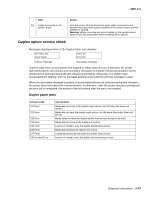
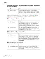
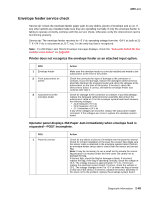
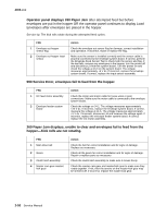
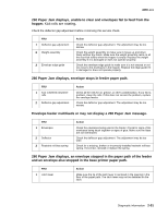
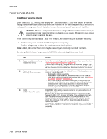
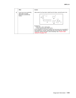
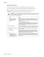
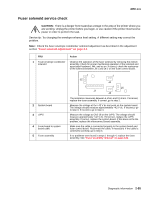
4060-xxx Operator panel displays 260 Paper Jam after attempted feed but before envelopes are put in the hopper OR the operator panel continues to display Load Envelopes after envelopes are placed in the hopper. Service tip: The kick rolls rotate during the attempted feed cycles. FRU 1 Envelope out hopper sensor flag 2 Envelope out hopper input sensor Action Check the envelope out sensor flag for damage, correct installation and operation. If incorrect, repair or replace the flag. Make sure the sensor is installed correctly and the sensor cable is properly connected to the envelope system board. If correct, perform the Envelope Feed Sensor Test to check both the sensor and flag. If the test fails, remove any envelopes in the hopper, turn the printer off and disconnect J3 from the system board. Turn the printer on and check the voltage at J3-3 on the system board. The voltage measures approximately +5 V dc. If incorrect, replace the envelope system board. If correct, replace the input sensor assembly. 990 Service Error, envelopes fail to feed from the hopper. FRU 1 DC feed motor assembly 2 Envelope feeder system board Action Check the motor and motor cable for loose wires or poor connections. Make sure the motor cable is connected to the envelope system board. Check the voltage on J4-1. The voltage measures approximately +24 V dc. If incorrect, replace the envelope system board. If correct, measure the voltage at J4-6. The voltage measures approximately +5 V dc. If incorrect, disconnect J4 and measure the voltage again. If incorrect, replace the envelope feeder system board. If correct, replace the DC motor assembly. 260 Paper Jam displays, unable to clear and envelopes fail to feed from the hopper-Kick rolls are not rotating. FRU 1 Main drive belt 2 Gears 3 Clutch latch assembly 4 Master cam gear master/ kick gear Action Check the belt for correct installation and for signs of damage. Replace as necessary. Check all the gears for correct installation and for signs of damage. Repair or replace parts as necessary. Check the clutch latch assembly to make sure it moves freely. Check the master cam gear and master/kick gear to make sure they rotate together. If not, then the tenons on the master kick gear may be sheared off. If incorrect, replace the master kick gear. 2-50 Service Manual
-
 1
1 -
2
-
3
-
4
-
5
-
6
-
7
-
8
-
9
-
10
-
11
-
12
-
13
-
14
-
15
-
16
-
17
-
18
-
19
-
20
-
21
-
22
-
23
-
24
-
25
-
26
-
27
-
28
-
29
-
30
-
31
-
32
-
33
-
34
-
35
-
36
-
37
-
38
-
39
-
40
-
41
-
42
-
43
-
44
-
45
-
46
-
47
-
48
-
49
-
50
-
51
-
52
-
53
-
54
-
55
-
56
-
57
-
58
-
59
-
60
-
61
-
62
-
63
-
64
-
65
-
66
-
67
-
68
-
69
-
70
-
71
-
72
-
73
-
74
-
75
-
76
-
77
-
78
-
 79
79 -
 80
80 -
 81
81 -
 82
82 -
 83
83 -
 84
84 -
 85
85 -
 86
86 -
 87
87 -
 88
88 -
 89
89 -
90
-
91
-
92
-
93
-
94
-
95
-
96
-
97
-
98
-
99
-
100
-
101
-
102
-
103
-
104
-
105
-
106
-
107
-
108
-
109
-
110
-
111
-
112
-
113
-
114
-
115
-
116
-
117
-
118
-
119
-
120
-
121
-
122
-
123
-
124
-
125
-
126
-
127
-
128
-
129
-
130
-
131
-
132
-
133
-
134
-
135
-
136
-
137
-
138
-
139
-
140
-
141
-
142
-
143
-
144
-
145
-
146
-
147
-
148
-
149
-
150
-
151
-
152
-
153
-
154
-
155
-
156
-
157
-
158
-
159
-
160
-
161
-
162
-
163
-
164
-
165
-
166
-
167
-
168
-
169
-
170
-
171
-
172
-
173
-
174
-
175
-
176
-
177
-
178
-
179
-
180
-
181
-
182
-
183
-
184
-
185
-
186
-
187
-
188
-
189
-
190
-
191
-
192
-
193
-
194
-
195
-
196
-
197
-
198
-
199
-
200
-
201
-
202
-
203
-
204
-
205
-
206
-
207
-
208
-
209
-
210
-
211
-
212
-
213
-
214
-
215
-
216
-
217
-
218
-
219
-
220
-
221
-
222
-
223
-
224
-
225
-
226
-
227
-
228
-
229
-
230
-
231
-
232
-
233
-
234
-
235
-
236
-
237
-
238
-
239
-
240
-
241
-
242
-
243
-
244
-
245
-
246
-
247
-
248
-
249
-
250
-
251
-
252
-
253
-
254
-
255
-
256
-
257
-
258
-
259
-
260
-
261
-
262
-
263
-
264
-
265
-
266
-
267
-
268
-
269
-
270
-
271
-
272
-
273
-
274
-
275
-
276
-
277
-
278
-
279
-
280
-
281
-
282
-
283
-
284
-
285
-
286
-
287
-
288
-
289
-
290
-
291
-
292
-
293
-
294
-
295
-
296
-
297
-
298
-
299
-
300
-
301
-
302
-
303
-
304
-
305
-
306
-
307
-
308
-
309
-
310
-
311
-
312
-
313
-
314
-
315
-
316
-
317
-
318
-
319
-
320
-
321
-
322
-
323
-
324
-
325
-
326
-
327
-
328
-
329
-
330
-
331
-
332
-
333
-
334
-
335
-
336
-
337
-
338
-
339
-
340
-
341
-
342
-
343
-
344
-
345
 |
 |
