Lexmark T632 Service Manual - Page 80
Warning, Action, Low voltage power supply, removal
 |
View all Lexmark T632 manuals
Add to My Manuals
Save this manual to your list of manuals |
Page 80 highlights
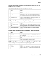
4060-xxx FRU 5 LVPS Action Unplug the AC line cord from the LVPS and disconnect the interconnect card cable on the LVPS. Reconnect the AC line cord and measure the voltage on CN2-1 on the LVPS. The voltage should measure approximately +5 V dc. CN2 6 Interconnect board 18 10 9 1 If the voltage is correct, go to step 6. If the voltage is incorrect, go to step 10. Unplug the AC line cord from the LVPS and reconnect the interconnect board cable to CN2 on the LVPS. Reconnect the AC line cord, turn the machine on and measure the voltage at the +5 V test point on the interconnect board. The voltage should read approximately +5 V dc. Test Points J4 +24V +5V J5 F1 F2 7 Interconnect board 8 Communications card 9 Features or option installed on the interconnect board assembly 10 LVPS fuse F1 (primary power) If correct, replace the following FRUs in the order shown: • System board • Interconnect board If the voltage is incorrect, go to step 7. Unplug the AC line cord from the LVPS, remove the inner shield and system board assembly from the interconnect board. Note: The inner shield with system board attached can be moved far enough away from the printer to access the interconnect board voltage test points. Measure the voltage at the +5 V test point on the interconnect board. The voltage should measure +5 V dc. If correct, go to step 11. If incorrect, go to step 8. Turn the printer off and remove the communications card. Check the voltage at the 5 V test point on the interconnect board. If the voltage is correct, replace the communication card assembly. If the voltage is incorrect, go to step 9. Warning: Observe all the ESD precautions and turn the printer off before any feature or option cards are removed or replaced. Remove one option/feature at a time to help isolate the failing part. Replace the faulty part. Unplug the AC line cord, remove the LVPS from the printer, and check the continuity of fuse F1. See "Low voltage power supply removal" on page 4-42. If continuity is correct, replace the LVPS assembly. If continuity is incorrect, replace fuse F1 and measure the voltage at CN2-1. If the voltage is correct, reconnect the interconnect board cable, reinstall the system board, and recheck the printer for a dead machine condition. If the printer is still inoperative, go to step 11. If the voltage is incorrect, replace the LVPS assembly. 2-46 Service Manual
-
 1
1 -
2
-
3
-
4
-
5
-
6
-
7
-
8
-
9
-
10
-
11
-
12
-
13
-
14
-
15
-
16
-
17
-
18
-
19
-
20
-
21
-
22
-
23
-
24
-
25
-
26
-
27
-
28
-
29
-
30
-
31
-
32
-
33
-
34
-
35
-
36
-
37
-
38
-
39
-
40
-
41
-
42
-
43
-
44
-
45
-
46
-
47
-
48
-
49
-
50
-
51
-
52
-
53
-
54
-
55
-
56
-
57
-
58
-
59
-
60
-
61
-
62
-
63
-
64
-
65
-
66
-
67
-
68
-
69
-
70
-
71
-
72
-
73
-
74
-
 75
75 -
 76
76 -
 77
77 -
 78
78 -
 79
79 -
 80
80 -
 81
81 -
 82
82 -
 83
83 -
 84
84 -
 85
85 -
86
-
87
-
88
-
89
-
90
-
91
-
92
-
93
-
94
-
95
-
96
-
97
-
98
-
99
-
100
-
101
-
102
-
103
-
104
-
105
-
106
-
107
-
108
-
109
-
110
-
111
-
112
-
113
-
114
-
115
-
116
-
117
-
118
-
119
-
120
-
121
-
122
-
123
-
124
-
125
-
126
-
127
-
128
-
129
-
130
-
131
-
132
-
133
-
134
-
135
-
136
-
137
-
138
-
139
-
140
-
141
-
142
-
143
-
144
-
145
-
146
-
147
-
148
-
149
-
150
-
151
-
152
-
153
-
154
-
155
-
156
-
157
-
158
-
159
-
160
-
161
-
162
-
163
-
164
-
165
-
166
-
167
-
168
-
169
-
170
-
171
-
172
-
173
-
174
-
175
-
176
-
177
-
178
-
179
-
180
-
181
-
182
-
183
-
184
-
185
-
186
-
187
-
188
-
189
-
190
-
191
-
192
-
193
-
194
-
195
-
196
-
197
-
198
-
199
-
200
-
201
-
202
-
203
-
204
-
205
-
206
-
207
-
208
-
209
-
210
-
211
-
212
-
213
-
214
-
215
-
216
-
217
-
218
-
219
-
220
-
221
-
222
-
223
-
224
-
225
-
226
-
227
-
228
-
229
-
230
-
231
-
232
-
233
-
234
-
235
-
236
-
237
-
238
-
239
-
240
-
241
-
242
-
243
-
244
-
245
-
246
-
247
-
248
-
249
-
250
-
251
-
252
-
253
-
254
-
255
-
256
-
257
-
258
-
259
-
260
-
261
-
262
-
263
-
264
-
265
-
266
-
267
-
268
-
269
-
270
-
271
-
272
-
273
-
274
-
275
-
276
-
277
-
278
-
279
-
280
-
281
-
282
-
283
-
284
-
285
-
286
-
287
-
288
-
289
-
290
-
291
-
292
-
293
-
294
-
295
-
296
-
297
-
298
-
299
-
300
-
301
-
302
-
303
-
304
-
305
-
306
-
307
-
308
-
309
-
310
-
311
-
312
-
313
-
314
-
315
-
316
-
317
-
318
-
319
-
320
-
321
-
322
-
323
-
324
-
325
-
326
-
327
-
328
-
329
-
330
-
331
-
332
-
333
-
334
-
335
-
336
-
337
-
338
-
339
-
340
-
341
-
342
-
343
-
344
-
345
 |
 |
