Lexmark T632 Service Manual - Page 79
Dead machine service check, Warning, CAUTION
 |
View all Lexmark T632 manuals
Add to My Manuals
Save this manual to your list of manuals |
Page 79 highlights
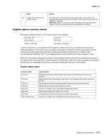
4060-xxx Dead machine service check A dead machine is a condition where the display is blank, the LED on the operator panel is off, no fans turn, no motors turn, and the fuser lamp does not come on. If a high-capacity input tray is installed, remove the option and check the base printer for correct operation. If the base printer operates correctly, go to "High-capacity feeder input tray service check" on page 2-56. If the base printer continues to not operate correctly, remove any other attached paper handling options. Warning: Observe all necessary ESD precautions when removing and handling the system board or any installed option cards or assemblies. See "Handling ESD-sensitive parts" on page 4-1. CAUTION: When you see this symbol, there is a danger from hazardous voltage in the area of the printer where you are working. Unplug the printer before you begin, or use caution if the printer must receive power in order to perform the task. Remove any input and output paper handling options from the printer. FRU 1 Line voltage 2 AC line cord 3 +5 V dc test point on the system board Action Check the AC line voltage. If the line voltage is incorrect, inform the customer. Unplug the line cord from the wall outlet and check the line cord for damage, such as, a damaged plug, or cut or damaged cord. If incorrect, replace the cord. If incorrect, check the continuity of the line cord and replace if necessary. If the cord is correct, go to step 3. Check for approximately +5 V dc at the +5 V test point on the system board. Note: Use care not to short adjacent voltage test points. 4 System board and interconnect board 1 J24 +42V +5V HEAT +24V +3.3V GND If the voltage is correct, replace the system board assembly. If the voltage is incorrect, go to step 4. Check the system board is firmly seated in connector J7 on the interconnect board. If it is not seated correctly, reseat and recheck the voltage at the +5 V dc test point on the system board. If test point does not measure +5 V dc, go to step 5. Diagnostic information 2-45
-
 1
1 -
2
-
3
-
4
-
5
-
6
-
7
-
8
-
9
-
10
-
11
-
12
-
13
-
14
-
15
-
16
-
17
-
18
-
19
-
20
-
21
-
22
-
23
-
24
-
25
-
26
-
27
-
28
-
29
-
30
-
31
-
32
-
33
-
34
-
35
-
36
-
37
-
38
-
39
-
40
-
41
-
42
-
43
-
44
-
45
-
46
-
47
-
48
-
49
-
50
-
51
-
52
-
53
-
54
-
55
-
56
-
57
-
58
-
59
-
60
-
61
-
62
-
63
-
64
-
65
-
66
-
67
-
68
-
69
-
70
-
71
-
72
-
73
-
 74
74 -
 75
75 -
 76
76 -
 77
77 -
 78
78 -
 79
79 -
 80
80 -
 81
81 -
 82
82 -
 83
83 -
 84
84 -
85
-
86
-
87
-
88
-
89
-
90
-
91
-
92
-
93
-
94
-
95
-
96
-
97
-
98
-
99
-
100
-
101
-
102
-
103
-
104
-
105
-
106
-
107
-
108
-
109
-
110
-
111
-
112
-
113
-
114
-
115
-
116
-
117
-
118
-
119
-
120
-
121
-
122
-
123
-
124
-
125
-
126
-
127
-
128
-
129
-
130
-
131
-
132
-
133
-
134
-
135
-
136
-
137
-
138
-
139
-
140
-
141
-
142
-
143
-
144
-
145
-
146
-
147
-
148
-
149
-
150
-
151
-
152
-
153
-
154
-
155
-
156
-
157
-
158
-
159
-
160
-
161
-
162
-
163
-
164
-
165
-
166
-
167
-
168
-
169
-
170
-
171
-
172
-
173
-
174
-
175
-
176
-
177
-
178
-
179
-
180
-
181
-
182
-
183
-
184
-
185
-
186
-
187
-
188
-
189
-
190
-
191
-
192
-
193
-
194
-
195
-
196
-
197
-
198
-
199
-
200
-
201
-
202
-
203
-
204
-
205
-
206
-
207
-
208
-
209
-
210
-
211
-
212
-
213
-
214
-
215
-
216
-
217
-
218
-
219
-
220
-
221
-
222
-
223
-
224
-
225
-
226
-
227
-
228
-
229
-
230
-
231
-
232
-
233
-
234
-
235
-
236
-
237
-
238
-
239
-
240
-
241
-
242
-
243
-
244
-
245
-
246
-
247
-
248
-
249
-
250
-
251
-
252
-
253
-
254
-
255
-
256
-
257
-
258
-
259
-
260
-
261
-
262
-
263
-
264
-
265
-
266
-
267
-
268
-
269
-
270
-
271
-
272
-
273
-
274
-
275
-
276
-
277
-
278
-
279
-
280
-
281
-
282
-
283
-
284
-
285
-
286
-
287
-
288
-
289
-
290
-
291
-
292
-
293
-
294
-
295
-
296
-
297
-
298
-
299
-
300
-
301
-
302
-
303
-
304
-
305
-
306
-
307
-
308
-
309
-
310
-
311
-
312
-
313
-
314
-
315
-
316
-
317
-
318
-
319
-
320
-
321
-
322
-
323
-
324
-
325
-
326
-
327
-
328
-
329
-
330
-
331
-
332
-
333
-
334
-
335
-
336
-
337
-
338
-
339
-
340
-
341
-
342
-
343
-
344
-
345
 |
 |
