Lexmark T632 Service Manual - Page 127
Toner sensor service check, Stapled sheets are not transported to the output tray.
 |
View all Lexmark T632 manuals
Add to My Manuals
Save this manual to your list of manuals |
Page 127 highlights
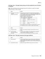
4060-xxx Stapled sheets are not transported to the output tray. FRU 1 Sol 2 (stapler gearbox assembly) Stapler card assembly Action Disconnect Sol 2 cable from J8 on the stapler card and measure the resistance of the solenoid across the cable connector. It should measure approximately 48 ohms (cold). If incorrect, replace the stapler/finisher option assembly. If correct, replace the stapler card assembly. POST incomplete-stapler cycles several times FRU 1 Stapler assembly Action Replace the stapler assembly. Note: When replacing the stapler assembly, observe the location of the ground lead from the stapler assembly and the finisher frame, and make sure the ground lead is correctly reattached. (Flag or spring off stapler unit) Will also happen when pin 7 of J3 is open. Toner sensor service check Service tip: Check the print darkness menu setting before checking the toner sensor. This service check is intended to be used when a 929 Service Error displays. FRU 1 Developer drive assembly 2 Front harness cable 3 Toner sensor Action Incorrect operation of the developer drive assembly can cause the printer to display a 929 error code (Toner Sensor). Check the developer drive assembly for correct installation, any sign of worn, loose, or broken parts. Check the toner sensor portion of the front harness cable to make sure it is properly seated into the toner sensor. If correct at both the sensor and system board (J22), check the continuity of the cable. If incorrect, replace the cable. The toner sensor cable is part of the front harness and part of connector J22 on the system board. Check the voltage at J22-11. It reads approximately +5 V dc. If incorrect, replace the system board. If correct, check the voltage at J22-12. It reads approximately +5 V dc with the system board removed from the printer. If incorrect, replace the system board. If correct, replace the toner sensor assembly. A bad ground connection between J22-13 on the system board and pin 3 on the toner sensor results in a 929 service error. Diagnostic information 2-93
-
 1
1 -
2
-
3
-
4
-
5
-
6
-
7
-
8
-
9
-
10
-
11
-
12
-
13
-
14
-
15
-
16
-
17
-
18
-
19
-
20
-
21
-
22
-
23
-
24
-
25
-
26
-
27
-
28
-
29
-
30
-
31
-
32
-
33
-
34
-
35
-
36
-
37
-
38
-
39
-
40
-
41
-
42
-
43
-
44
-
45
-
46
-
47
-
48
-
49
-
50
-
51
-
52
-
53
-
54
-
55
-
56
-
57
-
58
-
59
-
60
-
61
-
62
-
63
-
64
-
65
-
66
-
67
-
68
-
69
-
70
-
71
-
72
-
73
-
74
-
75
-
76
-
77
-
78
-
79
-
80
-
81
-
82
-
83
-
84
-
85
-
86
-
87
-
88
-
89
-
90
-
91
-
92
-
93
-
94
-
95
-
96
-
97
-
98
-
99
-
100
-
101
-
102
-
103
-
104
-
105
-
106
-
107
-
108
-
109
-
110
-
111
-
112
-
113
-
114
-
115
-
116
-
117
-
118
-
119
-
120
-
121
-
 122
122 -
 123
123 -
 124
124 -
 125
125 -
 126
126 -
 127
127 -
 128
128 -
 129
129 -
 130
130 -
 131
131 -
 132
132 -
133
-
134
-
135
-
136
-
137
-
138
-
139
-
140
-
141
-
142
-
143
-
144
-
145
-
146
-
147
-
148
-
149
-
150
-
151
-
152
-
153
-
154
-
155
-
156
-
157
-
158
-
159
-
160
-
161
-
162
-
163
-
164
-
165
-
166
-
167
-
168
-
169
-
170
-
171
-
172
-
173
-
174
-
175
-
176
-
177
-
178
-
179
-
180
-
181
-
182
-
183
-
184
-
185
-
186
-
187
-
188
-
189
-
190
-
191
-
192
-
193
-
194
-
195
-
196
-
197
-
198
-
199
-
200
-
201
-
202
-
203
-
204
-
205
-
206
-
207
-
208
-
209
-
210
-
211
-
212
-
213
-
214
-
215
-
216
-
217
-
218
-
219
-
220
-
221
-
222
-
223
-
224
-
225
-
226
-
227
-
228
-
229
-
230
-
231
-
232
-
233
-
234
-
235
-
236
-
237
-
238
-
239
-
240
-
241
-
242
-
243
-
244
-
245
-
246
-
247
-
248
-
249
-
250
-
251
-
252
-
253
-
254
-
255
-
256
-
257
-
258
-
259
-
260
-
261
-
262
-
263
-
264
-
265
-
266
-
267
-
268
-
269
-
270
-
271
-
272
-
273
-
274
-
275
-
276
-
277
-
278
-
279
-
280
-
281
-
282
-
283
-
284
-
285
-
286
-
287
-
288
-
289
-
290
-
291
-
292
-
293
-
294
-
295
-
296
-
297
-
298
-
299
-
300
-
301
-
302
-
303
-
304
-
305
-
306
-
307
-
308
-
309
-
310
-
311
-
312
-
313
-
314
-
315
-
316
-
317
-
318
-
319
-
320
-
321
-
322
-
323
-
324
-
325
-
326
-
327
-
328
-
329
-
330
-
331
-
332
-
333
-
334
-
335
-
336
-
337
-
338
-
339
-
340
-
341
-
342
-
343
-
344
-
345
 |
 |
