Sharp AR M550N Installation Manual
Sharp AR M550N - B/W Laser - Copier Manual
 |
View all Sharp AR M550N manuals
Add to My Manuals
Save this manual to your list of manuals |
Sharp AR M550N manual content summary:
- Sharp AR M550N | Installation Manual - Page 1
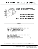
INSTALLATION MANUAL CODE : 00ZAR700//I1E DIGITAL LASER COPIER/PRINTER DIGITAL MULTIFUNCTIONAL SYSTEM AR-M550N/M550U AR-M620N/M620U MODEL AR-M700N/M700U CONTENTS [ 1 ] AR-M550/M620 UNPACKING AND INSTALLATION 1 - 1 [ 2 ] AR-LC6 UNPACKING AND INSTALLATION 2 - 1 [ 3 ] AR-CF2 UNPACKING AND - Sharp AR M550N | Installation Manual - Page 2
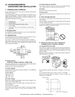
the humidity is too high, paper absorbs humidity to cause a paper jam or dirty copy. C. Power source (Capacity, voltage, frequency, safety, plug) If the power specifications are not satisfied, the machine cannot exhibit full performances and may cause safety trouble. Strictly observe the following - Sharp AR M550N | Installation Manual - Page 3
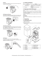
to the copier machine, copy images may be deflected and a trouble may be caused. 1 PP band 2 Top case 3 Pack case 4 Skid pad 5 Top pad R 6 Top pad L 7 Polyethylene bag 8 Bottom case unit 9 Accessory unit 10 Paper exit tray AS 11 Operation manual AR-M550/M620/M700 INSTALLATION MANUAL (AR-M550/M620 - Sharp AR M550N | Installation Manual - Page 4
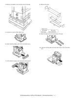
slope to the concave section of the skid. 6) Lift the machine slightly, and remove the bottom pad L. 10) Hold the machine grips and push them down in the arrow direction. 7) Lift the machine slightly, and remove the bottom pad R. AR-M550/M620/M700 INSTALLATION MANUAL (AR-M550/M620/M700) 1 - 3 - Sharp AR M550N | Installation Manual - Page 5
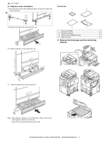
unit. 3 4 1 Driver (CD-ROM) x 1 2 Operation manual x 1 3 Delivery and installation report x 1 4 Paper exit tray x 1 machine includes a hard disk drive, which must be protected against vibrations and shocks. Never move the machine with the power ON. AR-M550/M620/M700 INSTALLATION MANUAL (AR - Sharp AR M550N | Installation Manual - Page 6
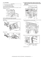
door to pull out the left door. 2 (2) Tray rotation release plate lock release Remove the paper feed tray rotation plate fixing screw and the label of note for tray. [Tray 1, Tray from the process unit. 4) Replace the left door. AR-M550/M620/M700 INSTALLATION MANUAL (AR-M550/M620/M700) 1 - 5 - Sharp AR M550N | Installation Manual - Page 7
(2) Toner set 1) Remove the toner cartridge toner hopper in the developing unit. 2) Insert the toner cartridge into the main unit insertion port as shown below. In this case, do not turn the cartridge. 3) Insert the toner cartridge until it is locked. AR-M550/M620/M700 INSTALLATION MANUAL (AR - Sharp AR M550N | Installation Manual - Page 8
Note: The 70-sheet machine (AR-M700N/U) performs resetting after normal completion of toner concentration control level setting operation (3 min) by SIM25-2, and supplies toner during warming up when the fuser heater lamp is turned ON in order to increase the toner concentration level by 0.5%. When - Sharp AR M550N | Installation Manual - Page 9
contact with the manual paper feed guide. Note: If there is any gap between paper and the manual paper feed guide, skew feed or wrinkles may be caused. Be sure to set paper so that there is no gap between paper and the guide. (4) Tray 2 paper size change When changing the paper size of the tray - Sharp AR M550N | Installation Manual - Page 10
used. 1) Remove the exclusive-use guide from the storage position left inside of the machine. 5) Push the tray 3. (7) Setting the paper type and paper size Follow these steps to change the paper type setting when the paper type has been changed in a paper tray. For the paper types that can be used - Sharp AR M550N | Installation Manual - Page 11
and "DISABLE DUPLEX" cannot be simultaneously enabled. 10) Configure paper settings for each tray and then touch the [OK] key to exit. Note: The size and type of paper loaded in the bypass tray can also be set from the paper setting screen. Touch the [PAPER SELECT] key in the main screen to display - Sharp AR M550N | Installation Manual - Page 12
between the screens. 4) Touch the [OK] key. (You will return to the size setting screen of step 2.) SIZE 81/2X14 1/4X101/2 TYPE 81/2X11 51/2X81/2R OK 1/2 5) Perform steps 7 through 10 of "Setting the paper type and paper size". AR-M550/M620/M700 INSTALLATION MANUAL (AR-M550/M620/M700) 1 - 11 - Sharp AR M550N | Installation Manual - Page 13
be used to change the paper size by software.) A3 paper 1 count/2 count setting Used to set the count mode of the total counter, the developer counter, and the maintenance counter. Specifications depending on the destination Used to set YES/NO of toner save operation. (This function is valid only - Sharp AR M550N | Installation Manual - Page 14
all the following parts are packaged. • Check that the printer is in stand-by state. Check that the DATA indicator on the operation panel is neither lit nor blinking. B. Attach the upper rear side of the main unit with two fixing screws B. AR-M550/M620/M700 INSTALLATION MANUAL (AR-LC6) 2 - 1 - Sharp AR M550N | Installation Manual - Page 15
feed tray. 2) Remove the paper feed base fixing screw (1 pc.) of the large capacity tray. 3) Push the large capacity tray slowly into the original position. 2) Remove the fixing material from the packaged part, and remove the packaged part. AR-M550/M620/M700 INSTALLATION MANUAL (AR-LC6) 2 - 2 - Sharp AR M550N | Installation Manual - Page 16
of the front cover counterclockwise to loosen and check that the screw is free. 2) Hang the metal fixture of the large capacity tray on the lower "Check installation of tray 5" is displayed on the operation panel. ∗ Push the large capacity tray onto the machine, and lock it securely. [Note] Note 1): - Sharp AR M550N | Installation Manual - Page 17
a b R side H. Select the paper size. (1) Change A4 size to LT size The factory setting of the paper size is A4. To select another size of the paper feed tray to disable the stopper function. 3) Then pull out the paper feed tray again until it stops. AR-M550/M620/M700 INSTALLATION MANUAL (AR-LC6) - Sharp AR M550N | Installation Manual - Page 18
fixing screw (blue) on the right side of the paper feed tray, and remove the rear edge shaft. 2) Tighten the removed rear edge shaft with the fixing screw (blue screw) and store it in the storage space inside the front cabinet. AR-M550/M620/M700 INSTALLATION MANUAL (AR-LC6) 2 - 5 [When LT size] - Sharp AR M550N | Installation Manual - Page 19
the paper feed setting) by the key operations of the main unit. 1) The size selection menu of the large capacity tray is displayed on the operation panel message display. 2) Select the size number from the message menu and enter the number with the 10-key. AR-M550/M620/M700 INSTALLATION MANUAL (AR - Sharp AR M550N | Installation Manual - Page 20
Default Set range TRAY1 TRAY1 (LCC left side) Print off center adjustment position TRAY2 TRAY2 Print off center (LCC right adjustment position side) TRAY3 TRAY3 Print off center adjustment position TRAY4 TRAY4 Print off center adjustment position BPT Manual Print off center paper - Sharp AR M550N | Installation Manual - Page 21
. for each), and push the paper feed tray into the machine. Return the stopper to the original position, and fix it with the fixing screw (1 pc.). Slide the auxiliary guide in the direction of B by not shifted. Repeat this procedure as required. AR-M550/M620/M700 INSTALLATION MANUAL (AR-LC6) 2 - 8 - Sharp AR M550N | Installation Manual - Page 22
and open the upper door. 2) Remove the tape and remove the miramatte. 3) Remove the tape and remove the fixing member. (Removal of the parts included) AR-M550/M620/M700 INSTALLATION MANUAL (AR-CF2) 3 - 1 - Sharp AR M550N | Installation Manual - Page 23
it is not installed, perform procedure (4). (2) Removal of the connector between the main unit and the finisher 1) Remove the screw from the finisher connector connected to the left side of the main unit. 2) Disconnect the finisher connector. 2 1 AR-M550/M620/M700 INSTALLATION MANUAL (AR-CF2) 3 - 2 - Sharp AR M550N | Installation Manual - Page 24
joint harness connector, and remove the connector cover. 2 1 5) Remove the paper exit cover on the upper side of the left door. ∗ Only when the finisher and the inserter are installed together, perform this procedure. 6) Close the left door. AR-M550/M620/M700 INSTALLATION MANUAL (AR-CF2) 3 - 3 - Sharp AR M550N | Installation Manual - Page 25
the two fixing screws E. (5) Install the positioning plate and the button cover to the finisher 1) Remove the step screw (1 pc) and the screws (2 pcs.) which are fixing the punch cover. .) to hide the lock button on the top of the punch cover. AR-M550/M620/M700 INSTALLATION MANUAL (AR-CF2) 3 - 4 - Sharp AR M550N | Installation Manual - Page 26
the inserter. 1) Set all the finisher height adjustment screws (4 positions) to the center positions. 2) Insert the inserter to the finisher. (Refer to the procedure (7) in this section.) (8) Fix the extension guide of the tray 1) Pull out the extension guide of the inserter paper feed tray until - Sharp AR M550N | Installation Manual - Page 27
2) Check that the main unit positioning pin enters smoothly into the center of the inserter positioning guide. 3) Connect the inserter relay harness connector to the main unit connector, and tighten the connector screw to fix the connector. 2 1 AR-M550/M620/M700 INSTALLATION MANUAL (AR-CF2) 3 - 6 - Sharp AR M550N | Installation Manual - Page 28
inserter front cabinet and the finisher front cabinet. F 2) Check the height of the inserter rear cabinet and the finisher rear cabinet. 2) Turn guide. R Go to procedure 13. A. Adjust the height of the front side. 1) Open the finisher - Sharp AR M550N | Installation Manual - Page 29
. 5) Tighten the adjustment section fixing screws (2 pcs.). 6) Close the finisher front door lower, and close the inserter front door. B. Adjust the rear 1) Remove two screws which are fixing the base cover attached to the finisher rear side base section, and remove the base cover. 2) Loosen the - Sharp AR M550N | Installation Manual - Page 30
the front and a screw at the back) fixed to the front and the rear of the finisher base section. 3) Loosen the front side and the rear side adjustment section fixing screws (2 to the finisher. Please reuse rail and connector plate for inserter. AR-M550/M620/M700 INSTALLATION MANUAL (AR-CF2) 3 - 9 - Sharp AR M550N | Installation Manual - Page 31
main power switch, close the power cover, and close the front cabinet. 4) Turn ON the power switch on the right side of the main unit. AR-M550/M620/M700 INSTALLATION MANUAL (AR-CF2) 3 - 10 - Sharp AR M550N | Installation Manual - Page 32
top case. 4) Hold the upper section of the machine with two persons, and pull it up and stand it straight. (The machine is very heavy. Be careful.) 5) Remove the tape x 6) 7 Screw H (M4 x 10) 8 Screw I (M4 x 18) 2 pcs. 3 pcs. 2 pcs. 4 pcs. AR-M550/M620/M700 INSTALLATION MANUAL (AR-F15/F16) 4 - 1 - Sharp AR M550N | Installation Manual - Page 33
fixing member and the sheet. 10) Slowly bring the base section of the machine on the opposite side to contact with the floor. 11) Remove the vinyl the finisher. Remove the shipment locking material with red sticky note. 1) Remove the tape. 1 2 1 AR-M550/M620/M700 INSTALLATION MANUAL (AR-F15 - Sharp AR M550N | Installation Manual - Page 34
the each tape. 1 7) Remove the tape and remove the jam release door transit fixing member. 8) Remove the tape and remove the jam release door handle section transit fixing member. 3 1 2 rail section transit fixing members (4 positions). 2 AR-M550/M620/M700 INSTALLATION MANUAL (AR-F15/F16) 4 - 3 - Sharp AR M550N | Installation Manual - Page 35
. (It is located over the DIP switch.) ∗ The finisher tray moves to the screw fixing position. 5) Turn off the power of the main unit. 6) Reset the DIP switch to the original state. 7) Install the attachment direction of the positioning pin. AR-M550/M620/M700 INSTALLATION MANUAL (AR-F15/F16) 4 - 4 - Sharp AR M550N | Installation Manual - Page 36
open the left door. 2) Install the rail and the finisher with two screws G (M4 x 6). 2 1 4) Remove the paper exit cover on the upper side of the left door. (4) Caster adjustment A. Bring the finisher closer to the main unit and check that the guide pin of the main unit enters into the connection - Sharp AR M550N | Installation Manual - Page 37
fixing screws (2 pcs.) of the rear cover on the rear of the finisher, and remove the rear cover. 6) Turn the bolt with the removed spanner so that the guide pin is in the specified range of the scale. 3) Only for the AR-F15, remove the front cabinet lower fixing screws (2 pcs.). (At that - Sharp AR M550N | Installation Manual - Page 38
power switch, close the power cover, and close the front cabinet. 4) Turn ON the power switch on the right side of the main unit. 2mm AR-M550/M620/M700 INSTALLATION MANUAL (AR-F15/F16) 4 - 7 - Sharp AR M550N | Installation Manual - Page 39
[5] AR-PN4 UNPACKING AND INSTALLATION 1. Unpacking (1) Removal of the main unit Packaged parts (accessories) Punch position label 2 pcs. front cabinet, and turn OFF the main power switch. 3) Disconnect the power plug from the power outlet. AR-M550/M620/M700 INSTALLATION MANUAL (AR-PN4) 5 - 1 - Sharp AR M550N | Installation Manual - Page 40
finisher. (3) Paper guide disassembly 1) Remove the paper guide fixing screw (1 pc.) and remove the paper guide from the finisher. finisher PWB. 3) Remove the cabinet B fixing screws (2 pcs.) on the rear side of the finisher, and remove the rear cabinet B. AR-M550/M620/M700 INSTALLATION MANUAL (AR - Sharp AR M550N | Installation Manual - Page 41
main power switch. 1) Insert the power plug into the power outlet. ∗ The label attachment position shown above is based on the corner of the cabinet. AR-M550/M620/M700 INSTALLATION MANUAL (AR-PN4) 5 - 3 - Sharp AR M550N | Installation Manual - Page 42
2) Open the front cabinet, and open the power cover. 3) Turn ON the main power switch, close the power cover, and close the front cabinet. 4) Turn ON the power switch on the right side of the main unit. AR-M550/M620/M700 INSTALLATION MANUAL (AR-PN4) 5 - 4 - Sharp AR M550N | Installation Manual - Page 43
unit out of the main unit. Print server card: 1 pc. BOOT ROM: 1 pc. ··· Printer utility CD-ROM: 1 pc. Network utility CD-ROM: 1 pc. Product key sheet: 1 sheet (1) Turn off the switches of the been removed. Cover Print server card Screws AR-M550/M620/M700 INSTALLATION MANUAL (AR-P19) 6 - 1 - Sharp AR M550N | Installation Manual - Page 44
key operator programs to carry out the network setting for this machine. For this network setting, the customer's network environment must be checked. Consult the network administrator to carry out the setting. 3) According to the customer's network environment, install the printer driver software - Sharp AR M550N | Installation Manual - Page 45
1 : Jan. 9 2004 [7] AR-FR11 INSTALLATION • To enable the data security function, the product key must be acquired. • connected to the control PWB, remove all cables. MAIN ROM BOOT ROM Screws Upper right cabinet Notches AR-M550/M620/M700 INSTALLATION MANUAL (AR-FR11) 7 - 1 - Sharp AR M550N | Installation Manual - Page 46
see the section of key operator programs of the operation manual for the main unit. After completing product key entry, turn off the power switch and the main power switch of the main unit and then turn on the power switch and the main power switch again. (7) Make user settings of the data security - Sharp AR M550N | Installation Manual - Page 47
its setting must be performed by the customer or based on discussion with the customer. For installation of the driver software, see the installation guide. 3) Finally, execute printing from the computer server and check that printing is performed normally. AR-M550/M620/M700 INSTALLATION MANUAL (AR - Sharp AR M550N | Installation Manual - Page 48
(2) Check the operation of the scanner function. 1) Installation of the driver software to the computer server and its setting must be performed by the customer or based on discussion with the customer. 2) Finally, referring to the installation guide, set the destination profile. Send image data and - Sharp AR M550N | Installation Manual - Page 49
installation of AR-FX8, the MFP control PWB unit must have been installed. • Start installation after checking that the LINE indicator and the DATA indicator below it on the operation panel are locked and the connector is not inserted at an angle. AR-M550/M620/M700 INSTALLATION MANUAL (AR-FX8) 10 - 1 - Sharp AR M550N | Installation Manual - Page 50
interface cable behind the FAX box unit and connect it to the FAX box unit. Grip Upper right cabinet Cut-out portion FAX interface cable AR-M550/M620/M700 INSTALLATION MANUAL (AR-FX8) 10 - 2 - Sharp AR M550N | Installation Manual - Page 51
on the right side of the main unit. 13) Set the destination of the FAX. Switch the operation panel to the copy mode and use the key operation [P], [*], [C], and [*] to enter the simulation mode. Use the 10-key pad to enter "66" in the main code entry screen shown below and press the START key - Sharp AR M550N | Installation Manual - Page 52
image memory. * If an extended memory (AR-MM9) has been mounted in step 3), be sure to carry out this step. If no extended memory has been mounted, this step is not necessary. Switch the operation panel to the copy mode and use the key operation "10" in the sub-code entry screen shown below and - Sharp AR M550N | Installation Manual - Page 53
as a service part. 1) Open the front cabinet of the main unit, and cur off the counter cover with a cutter and pliers. 2) Connect the connector on the mechanical counter side with the connector on the main unit side. 3) Insert the mechanical counter into the main unit and fit it securely. AR-M550 - Sharp AR M550N | Installation Manual - Page 54
Part name Part code Q'ty 1 Dehumidifying heater switch QSW-C1030QCZZ 1 2 Supporter LSUPP0118FCZZ 4 3 Dehumidifying wire saddle. 4 1 2) Remove the rear cabinet. 2. Scanner dry heater installation No. Part name 1 Scanner dry heater (120V) Scanner dry heater (230V) 2 Screw (M3 x 4S tight - Sharp AR M550N | Installation Manual - Page 55
box. 6 5 5 8) Install the clamp, and install the dark box to the scanner base plate. 5 5) Remove the screws. 5 5 NOTE: When installing the dark box check to insure that the blade spring is in the original position. 6) Install the scanner dry heater. 4 3 4 3 2 1 2 9) Pass the SCN WH harness - Sharp AR M550N | Installation Manual - Page 56
1) Open the left under cabinet. Part code Q'ty LPLTM6021FCZZ 1 LHLDW1285FCZZ 1 PRDAR0087FCZZ 1 RHETP0117FCZZ 1 RHETP0122FCZZ XHBSE30P04000 4 XHBSD30P06000 2 3) Install the dry heater (paper feed trays 1, 2) unit. 4 4 7 3 1 2 5 6 8 AR-M550/M620/M700 DRY HEATER INSTALLATION 12 - 3 - Sharp AR M550N | Installation Manual - Page 57
6 7) Fix the harness with the snap band, and pass it through the edge saddle. 4) Remove the lower stage of the paper trays 3/4 paper feed unit. 8) Connect the connector to the dehumidifying heater relay PWB. 5) Remove the paper feed lower cover. AR-M550/M620/M700 DRY HEATER INSTALLATION 12 - 4 - Sharp AR M550N | Installation Manual - Page 58
SOLDER The PWB's of this model employs lead-free solder. The "LF" marks indicated on the PWB's and the Service Manual mean "Lead-Free" solder. The alphabet following the LF mark shows the kind of lead-free solder. Example: 5mm Lead-Free Solder composition code (Refer to the table at the right - Sharp AR M550N | Installation Manual - Page 59
type ou d'un type équivalent recommandé par le constructeur. Mettre au rebut les batteries usagées conformément aux instructions du fabricant. (Swedish) VARNING Explosionsfara vid felaktigt batteribyte. Använd samma batterityp eller en ekvivalent typ som rekommenderas av apparattillverkaren - Sharp AR M550N | Installation Manual - Page 60
Windows® 95, Windows® 98, Windows® Me, Windows NT® 4.0, Windows® 2000, and Windows® XP are trademarks or copyrights of Microsoft Corporation in the U.S.A. and other countries. • IBM and PC/AT are trademarks of International Business Machines respective owners. SHARP CORPORATION Digital Document
-
 1
1 -
 2
2 -
 3
3 -
 4
4 -
 5
5 -
 6
6 -
 7
7 -
8
-
9
-
10
-
11
-
12
-
13
-
14
-
15
-
16
-
17
-
18
-
19
-
20
-
21
-
22
-
23
-
24
-
25
-
26
-
27
-
28
-
29
-
30
-
31
-
32
-
33
-
34
-
35
-
36
-
37
-
38
-
39
-
40
-
41
-
42
-
43
-
44
-
45
-
46
-
47
-
48
-
49
-
50
-
51
-
52
-
53
-
54
-
55
-
56
-
57
-
58
-
59
-
60
 |
 |
CONTENTS
Parts marked with “
” are important for maintaining the safety of the machine. Be sure to replace these parts
with the replacement parts specified to maintain the safety and performance of the machine.
SHARP CORPORATION
This document has been published to be used
for after sales service only.
The contents are subject to change without notice.
INSTALLATION MANUAL
CODE : 00ZAR700//I1E
DIGITAL LASER COPIER/PRINTER
DIGITAL MULTIFUNCTIONAL SYSTEM
AR-M550N/M550U
AR-M620N/M620U
MODEL
AR-M700N/M700U
[ 1 ] AR-M550/M620 UNPACKING AND INSTALLATION . . . . . . . . . . 1 - 1
[ 2 ] AR-LC6 UNPACKING AND INSTALLATION . . . . . . . . . . . . . . . . 2 - 1
[ 3 ] AR-CF2 UNPACKING AND INSTALLATION . . . . . . . . . . . . . . . . 3 - 1
[ 4 ] AR-F15/F16 UNPACKING AND INSTALLATION . . . . . . . . . . . . . 4 - 1
[ 5 ] AR-PN4 UNPACKING AND INSTALLATION . . . . . . . . . . . . . . . . 5 - 1
[ 6 ]
AR-P19 INSTALLATION . . . . . . . . . . . . . . . . . . . . . . . . . . . . . . . . 6 - 1
[ 7 ]
AR-FR11 INSTALLATION . . . . . . . . . . . . . . . . . . . . . . . . . . . . . . . 7 - 1
[ 8 ]
AR-PK5 INSTALLATION . . . . . . . . . . . . . . . . . . . . . . . . . . . . . . . . 8 - 1
[ 9 ]
AR-NS3 INSTALLATION. . . . . . . . . . . . . . . . . . . . . . . . . . . . . . . . 9 - 1
[10] AR-FX8/AR-MM9 INSTALLATION . . . . . . . . . . . . . . . . . . . . . . . 10 - 1
[11]
MECHANICAL COUNTER INSTALLATION . . . . . . . . . . . . . . . . . 11-1
[12]
DRY HEATER INSTALLATION . . . . . . . . . . . . . . . . . . . . . . . . . . . 12-1
1
1
1
1
2
2