Sharp AR M550N Installation Manual - Page 30
Install the plate
 |
View all Sharp AR M550N manuals
Add to My Manuals
Save this manual to your list of manuals |
Page 30 highlights
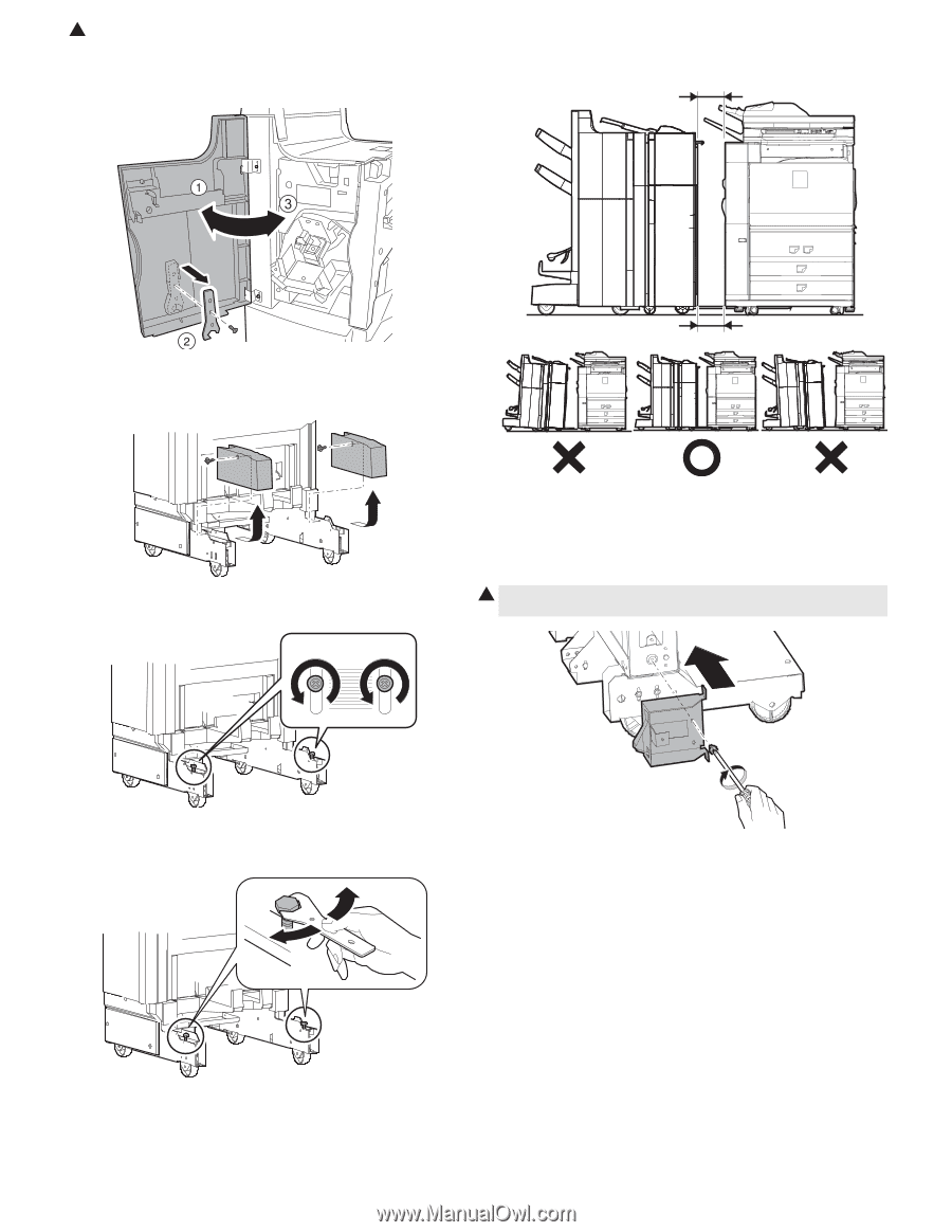
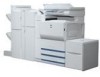
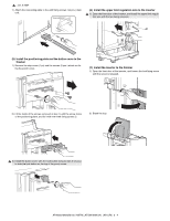
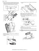
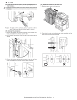
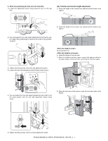
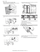
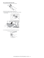
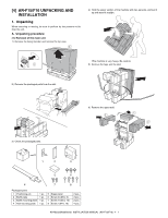
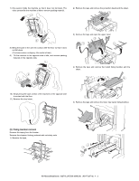
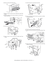
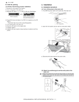
1 : Jan. 9 2004 • When the upper and the lower clearances differ: 1) Open the front upper door of the finisher, and remove the spanner (fixed with a screw) from the inside of the door. 5) Check that the upper and the lower clearances are even when viewed from the front and the back. 2) Remove the base cover (fixed with a screw in the front and a screw at the back) fixed to the front and the rear of the finisher base section. 3) Loosen the front side and the rear side adjustment section fixing screws (2 pcs. for each side). 6) Tighten the front and the rear side adjustment section fixing screws (2 pcs. for each side). 7) Install the base cover (front and rear). 8) Return the spanner to the original position. (14) Install the plate 1 1) Hang the plate on the rear lower side of the inserter as shown in the figure, and fix it with the fixing screw G (1 pc). 4) Turn the front and the rear side adjustment bolts with the spanner removed in step 1) so that the upper and the lower clearances are the same. ∗ At that time, check to insure that the upper and lower positioning tabs are in the plate holes. Remark: The plate and the connection plate are common to the finisher. Please reuse rail and connector plate for inserter. AR-M550/M620/M700 INSTALLATION MANUAL (AR-CF2) 3 - 9
-
 1
1 -
2
-
3
-
4
-
5
-
6
-
7
-
8
-
9
-
10
-
11
-
12
-
13
-
14
-
15
-
16
-
17
-
18
-
19
-
20
-
21
-
22
-
23
-
24
-
 25
25 -
 26
26 -
 27
27 -
 28
28 -
 29
29 -
 30
30 -
 31
31 -
 32
32 -
 33
33 -
 34
34 -
 35
35 -
36
-
37
-
38
-
39
-
40
-
41
-
42
-
43
-
44
-
45
-
46
-
47
-
48
-
49
-
50
-
51
-
52
-
53
-
54
-
55
-
56
-
57
-
58
-
59
-
60
 |
 |