Sharp AR M550N Installation Manual - Page 38
Attach the staple position label., Connect the finisher connector., Turn ON the main power switch.
 |
View all Sharp AR M550N manuals
Add to My Manuals
Save this manual to your list of manuals |
Page 38 highlights
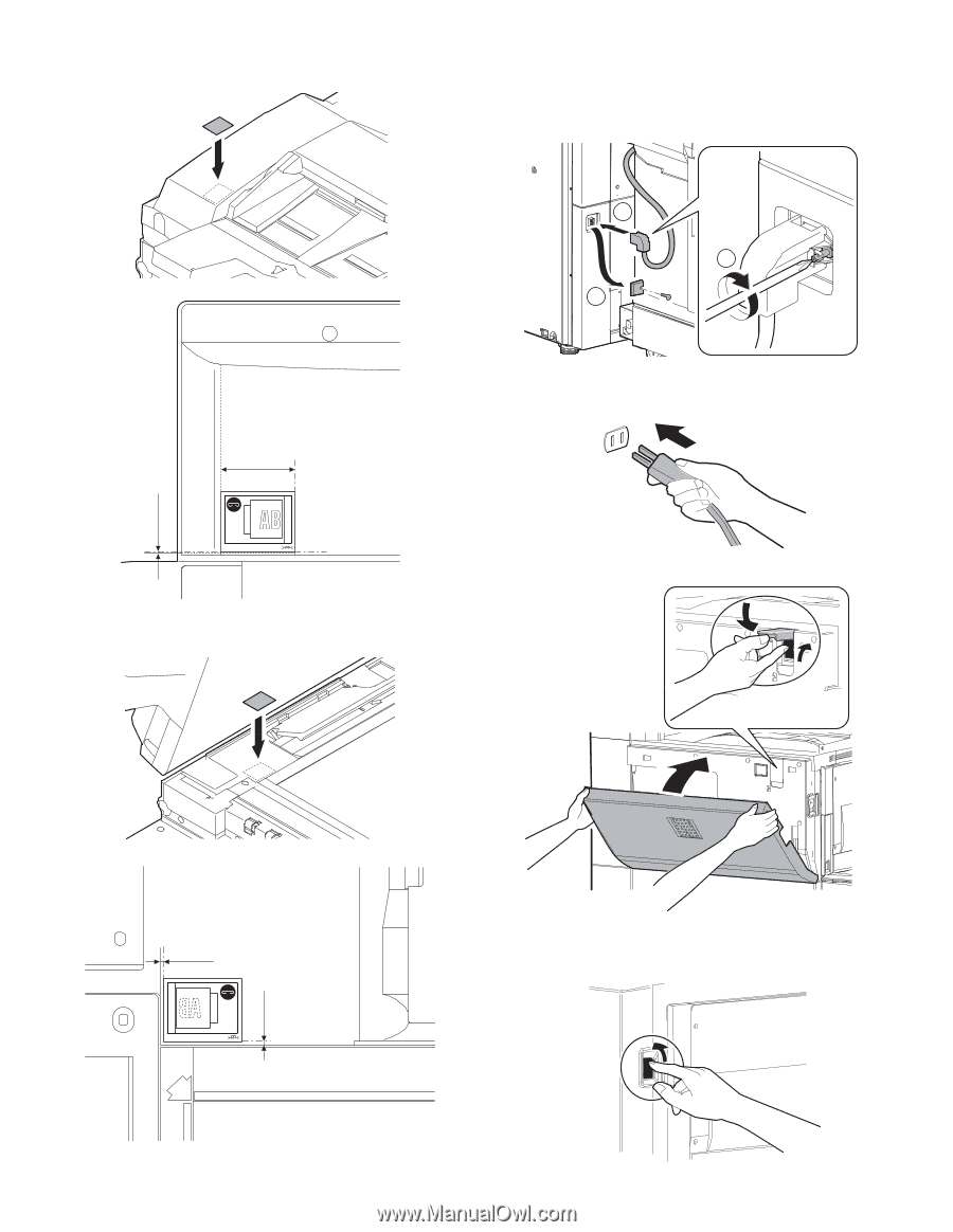
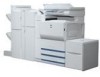
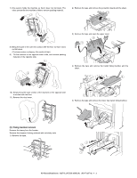
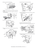
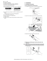
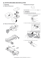
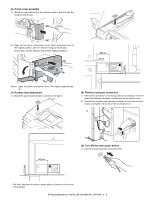
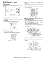
(5) Attach the staple position label. Attach the staple position label as shown in the figure. 40mm (6) Connect the finisher connector. A. Remove the connector cover fixing screw for connection of the finisher joint harness connector, and remove the connector cover. B. Connect the finisher relay harness connector to the main unit connector, and tighten the screw on the connector to fix. 2 3 1 (7) Turn ON the main power switch. 1) Insert the power plug of the main unit to the outlet. 0.5mm ∗ The label attachment position shown above is based on the corner of the cabinet. 2) Open the front cabinet, and open the power cover. 2mm 3) Turn ON the main power switch, close the power cover, and close the front cabinet. 4) Turn ON the power switch on the right side of the main unit. 2mm AR-M550/M620/M700 INSTALLATION MANUAL (AR-F15/F16) 4 - 7
-
 1
1 -
2
-
3
-
4
-
5
-
6
-
7
-
8
-
9
-
10
-
11
-
12
-
13
-
14
-
15
-
16
-
17
-
18
-
19
-
20
-
21
-
22
-
23
-
24
-
25
-
26
-
27
-
28
-
29
-
30
-
31
-
32
-
 33
33 -
 34
34 -
 35
35 -
 36
36 -
 37
37 -
 38
38 -
 39
39 -
 40
40 -
 41
41 -
 42
42 -
 43
43 -
44
-
45
-
46
-
47
-
48
-
49
-
50
-
51
-
52
-
53
-
54
-
55
-
56
-
57
-
58
-
59
-
60
 |
 |