Sharp AR M550N Installation Manual - Page 18
When LT size]
 |
View all Sharp AR M550N manuals
Add to My Manuals
Save this manual to your list of manuals |
Page 18 highlights
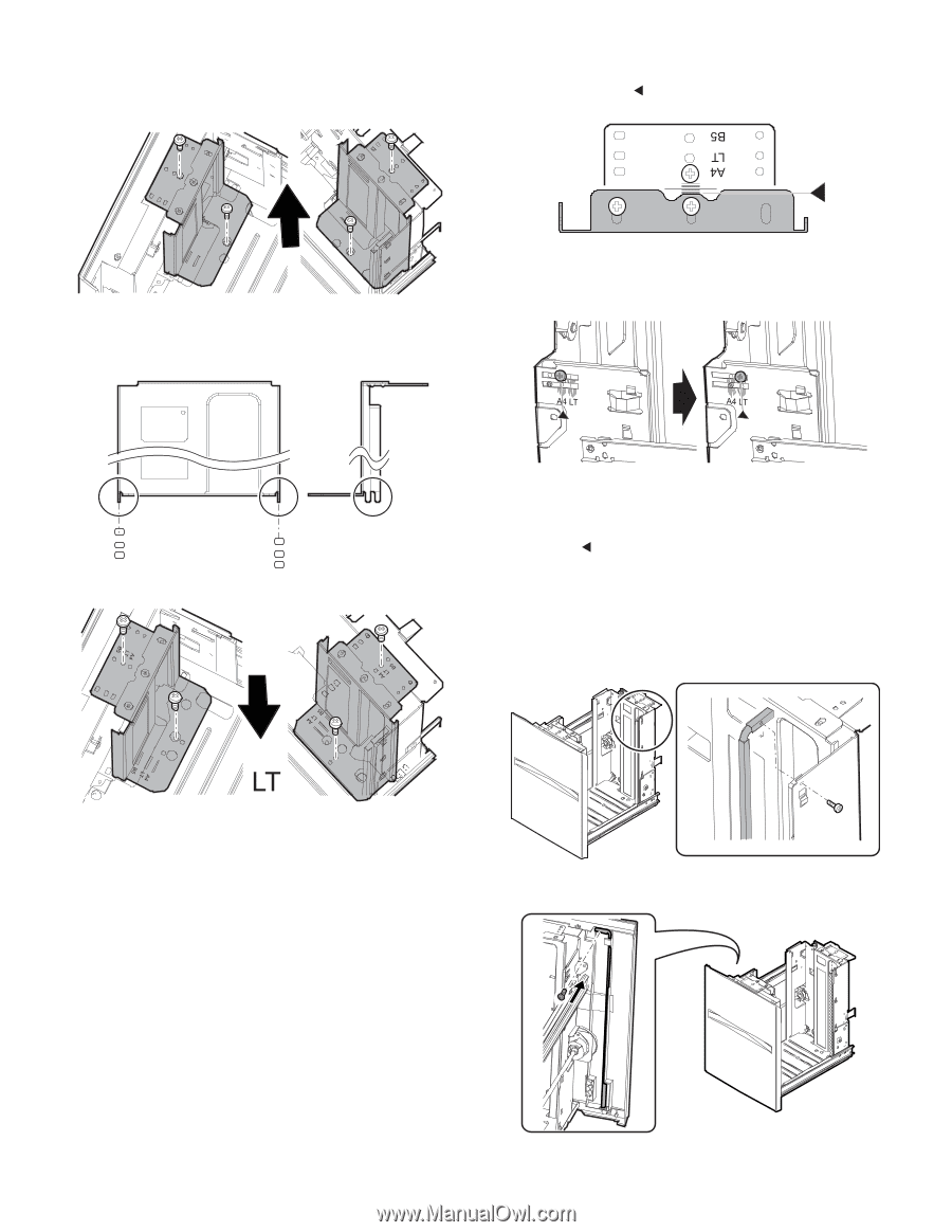
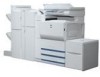
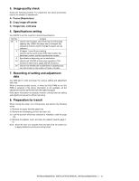
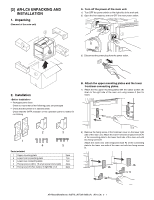
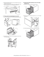
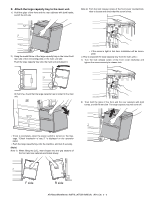
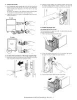
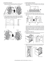
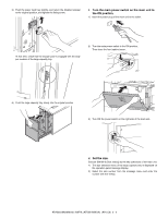
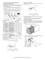
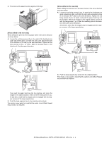
a. Side plate size change-over 1) Remove the four fixing screws (blue) which are fixing the upper and the lower sections of the side plate F and the side plate R. F side R side b. Auxiliary guide size change-over 1) When changing the size of the side plate R, check to confirm the mark positions of " " on the side plate R and the size guide adjustment plate. 2) Then fit the paper feed tray on the lower side of the side plate F and the side plate R with the engraved marks of the side plates according to the size, and insert it. Also fit the upper side to the size and fix it with the four fixing screws (blue). 2) Loosen the auxiliary guide fixing screw (Flat screw 1pc). 3) Change the mark position (v) of the auxiliary guide and the cassette R from A4 to LT, and fix them with the fixing screw (flat screw, 1pc). F side R side A4 LT At that time, adjust so that the mark positions (v) on the auxiliary guide and the cassette R are at the same positions of the mark positions ( ) of the side plate R and the size guide adjustment plate checked in the procedure 1). (If the scale of the size guide adjustment plate is at the center, set the position at the center. If is it at 1mm toward the front side, set the position at 1mm toward the front side.) c. Rear edge shaft change-over 1) Remove the rear edge shaft fixing screw (blue) on the right side of the paper feed tray, and remove the rear edge shaft. 2) Tighten the removed rear edge shaft with the fixing screw (blue screw) and store it in the storage space inside the front cabinet. AR-M550/M620/M700 INSTALLATION MANUAL (AR-LC6) 2 - 5 [When LT size]
-
 1
1 -
2
-
3
-
4
-
5
-
6
-
7
-
8
-
9
-
10
-
11
-
12
-
 13
13 -
 14
14 -
 15
15 -
 16
16 -
 17
17 -
 18
18 -
 19
19 -
 20
20 -
 21
21 -
 22
22 -
 23
23 -
24
-
25
-
26
-
27
-
28
-
29
-
30
-
31
-
32
-
33
-
34
-
35
-
36
-
37
-
38
-
39
-
40
-
41
-
42
-
43
-
44
-
45
-
46
-
47
-
48
-
49
-
50
-
51
-
52
-
53
-
54
-
55
-
56
-
57
-
58
-
59
-
60
 |
 |