Sharp AR M550N Installation Manual - Page 49
] Ar-fx8/ar-mm9 Installation - mfp control pwb
 |
View all Sharp AR M550N manuals
Add to My Manuals
Save this manual to your list of manuals |
Page 49 highlights
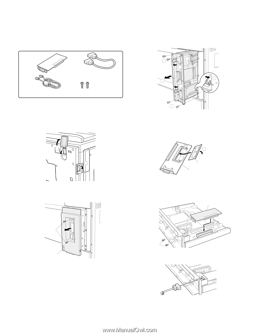
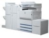
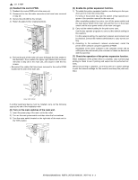
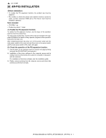
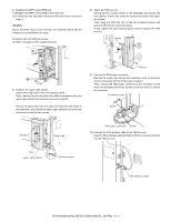
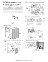
[10] AR-FX8/AR-MM9 INSTALLATION • For installation of AR-FX8, the MFP control PWB unit must have been installed. • Start installation after checking that the LINE indicator and the DATA indicator below it on the operation panel are neither lit nor blinking. Parts included FAX interface PWB unit (1 pc.) FAX interface cable (1 pc.) Line cable (1 pc.) Screw J (small) (2 pcs.) 1) Turn off the power switch of the main unit. Turn the power switch located on the right side of the main unit to the "OFF" position. Open the front cabinet and turn the main power switch to the "OFF" position. Remove the power plug of the main unit from the outlet. 2 1 2) Remove the MFP control PWB. Remove the two screws that secure the upper right cabinet and remove the upper right cabinet. Remove the four screws that secure the MFP control PWB unit to the main unit. Raise the two grips and hold them to pull out the MFP control PWB unit until the stopper is engaged. Remove the two flat cable connectors. While using your finger to release the stopper, pull the MFP control PWB unit out of the main unit. 2 4 3 5 5 3 2 * If you need not mount an extended memory, proceed to step 4). 3) Mount an extended memory. Mount an extended memory to the socket located on the back of the FAX interface PWB unit. 1 2 Extended memory FAX interface PWB unit 4) Attach the FAX interface PWB unit. Connect the FAX interface PWB unit to the FAX interface PWB connector (100 pin) on the MFP control PWB unit and secure it with two screws J. FAX interface PWB unit Screws Upper right cabinet Screws J 5) Connect the FAX interface cable. Connect the FAX interface cable to the MFP control PWB unit. Ensure that both ends of the connector are securely locked and the connector is not inserted at an angle. AR-M550/M620/M700 INSTALLATION MANUAL (AR-FX8) 10 - 1
-
 1
1 -
2
-
3
-
4
-
5
-
6
-
7
-
8
-
9
-
10
-
11
-
12
-
13
-
14
-
15
-
16
-
17
-
18
-
19
-
20
-
21
-
22
-
23
-
24
-
25
-
26
-
27
-
28
-
29
-
30
-
31
-
32
-
33
-
34
-
35
-
36
-
37
-
38
-
39
-
40
-
41
-
42
-
43
-
 44
44 -
 45
45 -
 46
46 -
 47
47 -
 48
48 -
 49
49 -
 50
50 -
 51
51 -
 52
52 -
 53
53 -
 54
54 -
55
-
56
-
57
-
58
-
59
-
60
 |
 |