Sharp AR M550N Installation Manual - Page 25
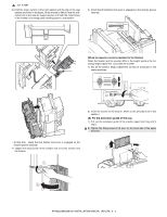
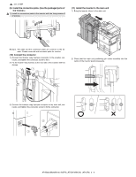
Install the upper limit regulation wire to the inserter
 |
View all Sharp AR M550N manuals
Add to My Manuals
Save this manual to your list of manuals |
Page 25 highlights
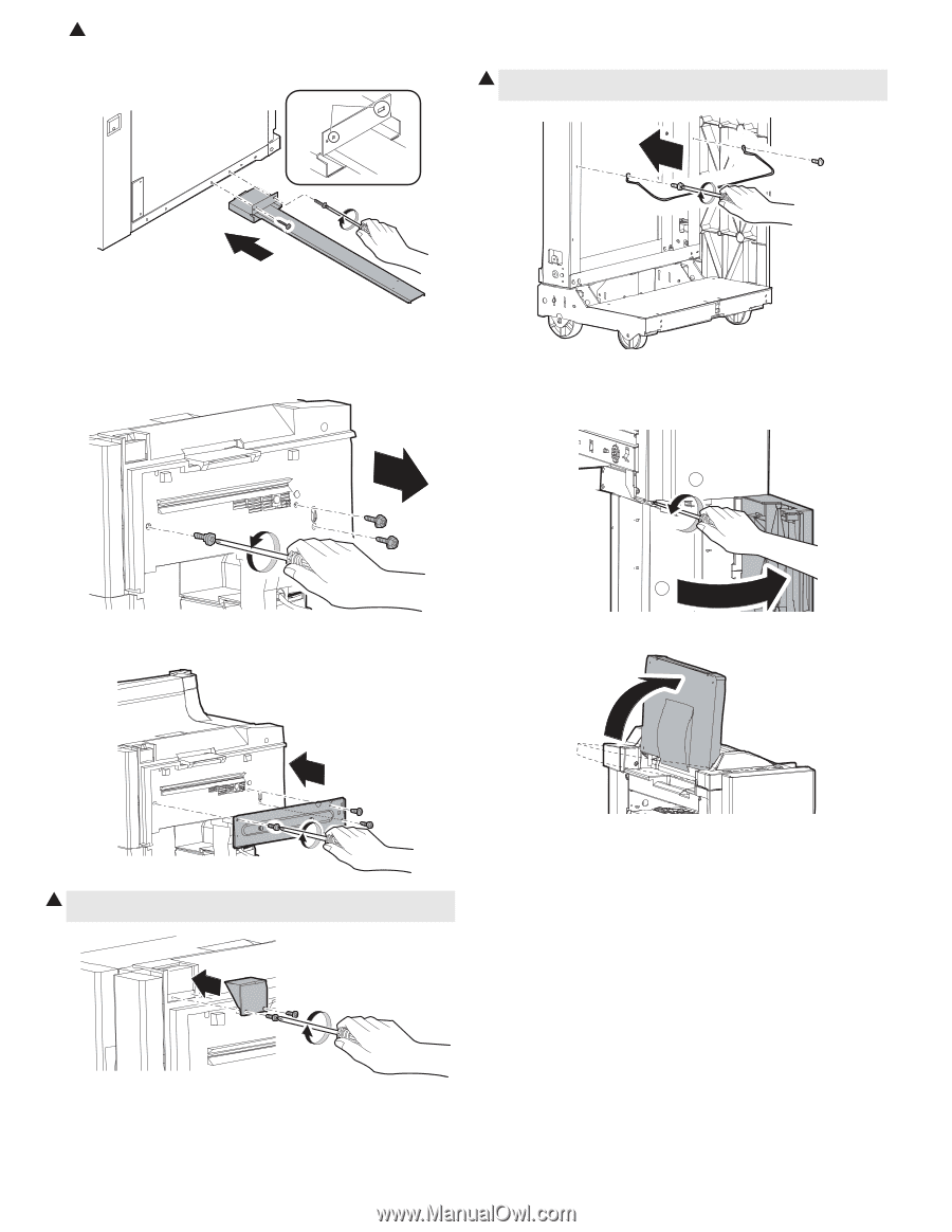
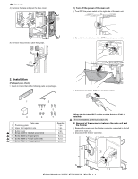
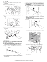
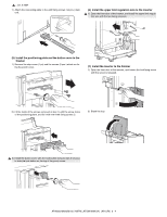
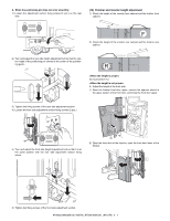
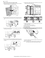
1 : Jan. 9 2004 7) Attach the connecting plate to the with fixing screws I (2 pcs.) main unit. Use positions (6) Install the upper limit regulation wire to the inserter 1 1) Open the front door of the inserter, and install the upper limit regulation wire with the two fixing screws E. (5) Install the positioning plate and the button cover to the finisher 1) Remove the step screw (1 pc) and the screws (2 pcs.) which are fixing the punch cover. (7) Install the inserter to the finisher 1) Open the front door of the inserter, and loosen the lock fixing screw until the screw is released. 2 1 2) Fit the holds of the screws removed in step 1) with the screw holes of the positioning plate, and fix it with the three fixing screws C. 2) Stand the tray. 1 3) Install the button cover with the lock button fixing screws D (2 pcs.) to hide the lock button on the top of the punch cover. AR-M550/M620/M700 INSTALLATION MANUAL (AR-CF2) 3 - 4
-
 1
1 -
2
-
3
-
4
-
5
-
6
-
7
-
8
-
9
-
10
-
11
-
12
-
13
-
14
-
15
-
16
-
17
-
18
-
19
-
 20
20 -
 21
21 -
 22
22 -
 23
23 -
 24
24 -
 25
25 -
 26
26 -
 27
27 -
 28
28 -
 29
29 -
 30
30 -
31
-
32
-
33
-
34
-
35
-
36
-
37
-
38
-
39
-
40
-
41
-
42
-
43
-
44
-
45
-
46
-
47
-
48
-
49
-
50
-
51
-
52
-
53
-
54
-
55
-
56
-
57
-
58
-
59
-
60
 |
 |