Sharp AR M550N Installation Manual - Page 21
Installation Manual
 |
View all Sharp AR M550N manuals
Add to My Manuals
Save this manual to your list of manuals |
Page 21 highlights
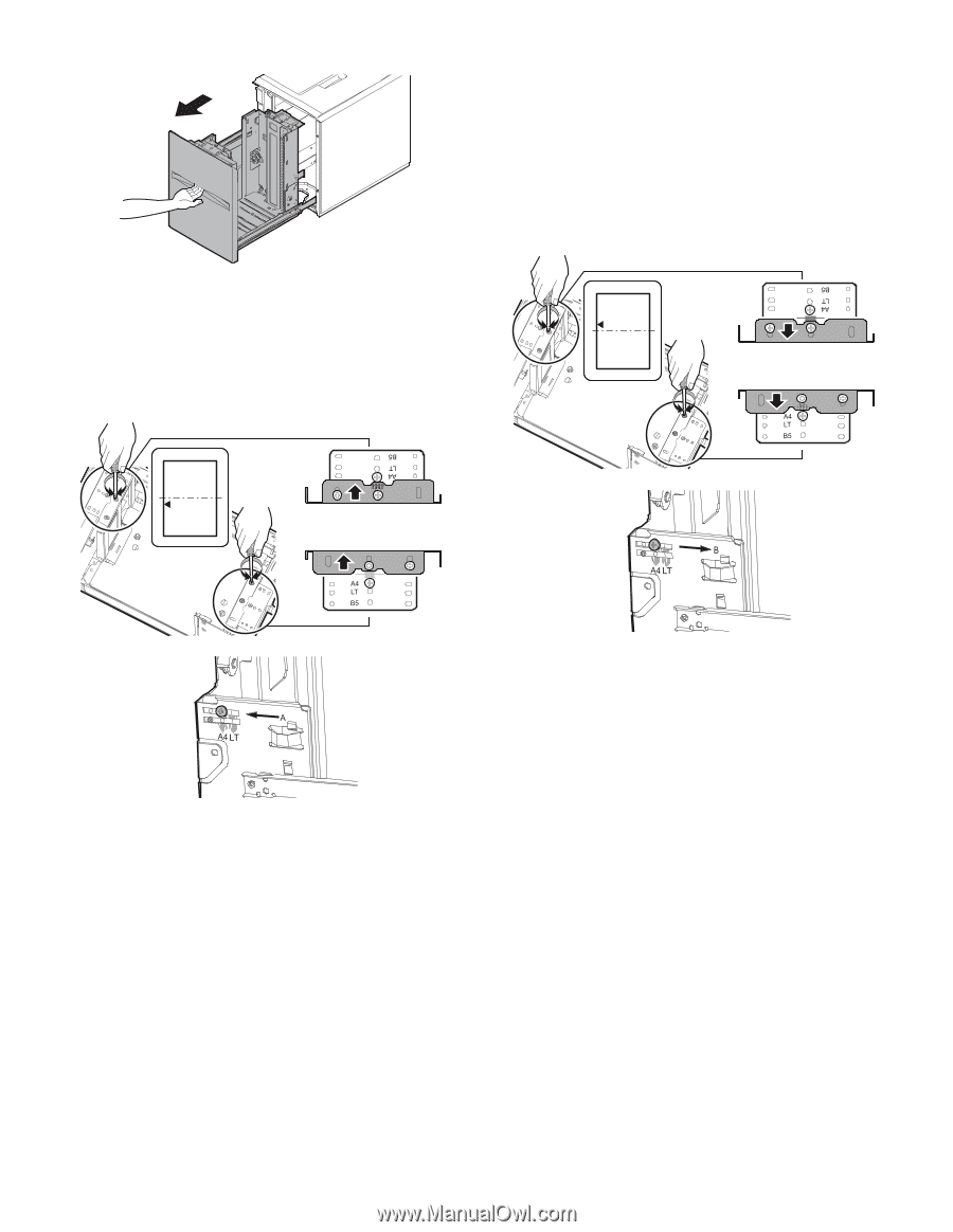
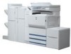
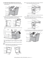
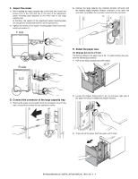
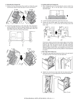
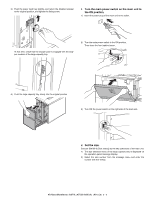
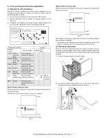
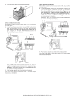
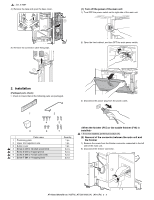
3) Then pull out the paper feed tray again until it stops. [When shifted to the front side] When shifting the print line from the paper center in the arrow direction as shown below: 4) Loosen the red fixing screws (2 pcs. for each) of the front/back size guide adjustment plate, and slide the side guide adjustment plate in the direction A (R side) by the shift dimension. Tighten the red fixing screws (2 pcs. for each). Slide the auxiliary guide in the direction of A by the same dimension. R side [When shifted to the rear side] When shifting the print line from the paper center in the arrow direction as shown below: 4) Loosen the red fixing screws (2 pcs. for each) of the front/back size guide adjustment plate, and slide the side guide adjustment plate in the direction B (F side) by the shift dimension. Tighten the red fixing screws (2 pcs. for each), and push the paper feed tray into the machine. Return the stopper to the original position, and fix it with the fixing screw (1 pc.). Slide the auxiliary guide in the direction of B by the same dimension. At that time, check that the stopper pawl is engaged with the stopper receiver of the large capacity tray. R side B F side A F side 5) Push the large capacity tray slowly into the original position. Then make a copy again to check that the center is not shifted. Repeat this procedure as required. Then push the paper feed tray into the machine, and return the stopper to the original position, and fix it with the fixing screw (1 pc.). At that time, check that the stopper pawl is engaged with the stopper receiver of the large capacity tray. 5) Push the large capacity tray to the original position slowly. Then make a copy again to check that the center is not shifted. Repeat this procedure as required. AR-M550/M620/M700 INSTALLATION MANUAL (AR-LC6) 2 - 8
-
 1
1 -
2
-
3
-
4
-
5
-
6
-
7
-
8
-
9
-
10
-
11
-
12
-
13
-
14
-
15
-
 16
16 -
 17
17 -
 18
18 -
 19
19 -
 20
20 -
 21
21 -
 22
22 -
 23
23 -
 24
24 -
 25
25 -
 26
26 -
27
-
28
-
29
-
30
-
31
-
32
-
33
-
34
-
35
-
36
-
37
-
38
-
39
-
40
-
41
-
42
-
43
-
44
-
45
-
46
-
47
-
48
-
49
-
50
-
51
-
52
-
53
-
54
-
55
-
56
-
57
-
58
-
59
-
60
 |
 |