Sharp AR M550N Installation Manual - Page 56
Dry heater Paper feed trays 1, 2, installation, Dry heater paper feed trays 3, 4
 |
View all Sharp AR M550N manuals
Add to My Manuals
Save this manual to your list of manuals |
Page 56 highlights
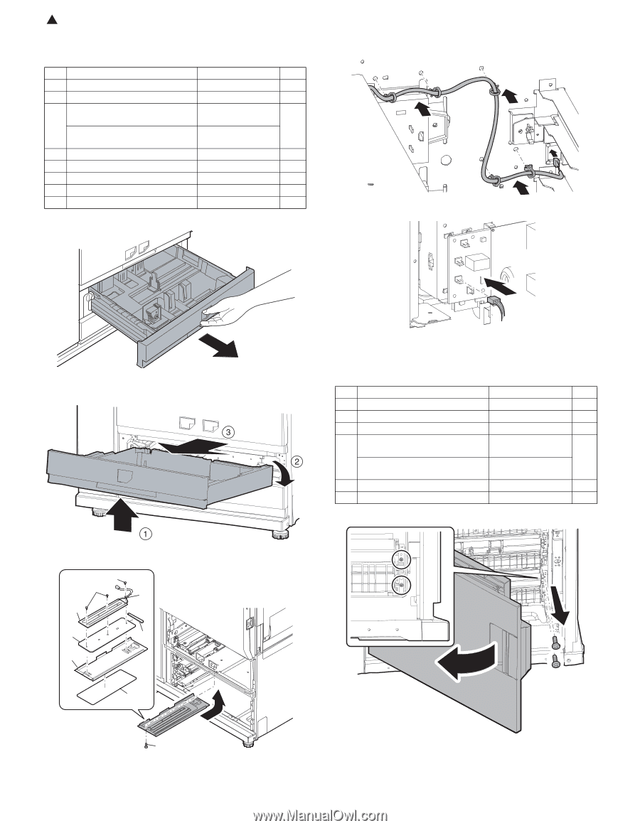
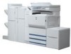
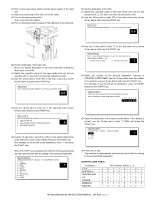
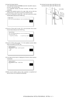
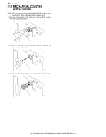
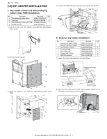
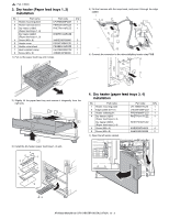
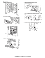
2 : Feb. 9 2004 3. Dry heater (Paper feed trays 1, 2) installation No. Part name 1 Heater mounting plate 2 Heater harness sheet 3 Dry heater (120V) (Paper feed trays 1, 2) Dry heater (230V) (Paper feed trays 1, 2) 4 Screw (M3 x 8) 5 Heater cover 6 Heater cover sheet 7 Heat-resistant clamp 8 Screw (M4 x 8) Part code Q'ty LPLTM6089FCZZ 1 PSHEZ5135FCZZ 1 RHETP0118FCZZ 1 RHETP0123FCZZ XHBSD30P08000 3 PCOVP1654FCZ1 1 PSHEZ5012FCZZ 1 LHLDW0433FCZZ 1 XHBSE40P08000 1 1) Pull out the paper feed tray until it stops. 4) Fix the harness with the snap band, and pass it through the edge saddle. 5) Connect the connector to the dehumidify8ing heater relay PWB. 2) Slightly lift the paper feed tray and remove it diagonally from the right side. 4. Dry heater (paper feed trays 3, 4) installation No. Part name 1 Heater mounting plate 2 Edge saddle (EH11) 3 Heater radiating fin 4 Dry heater (120V) (Paper feed trays 3, 4) Dry heater (230V) (Paper feed trays 3, 4) 5 Screw (M3 x 4) 6 Screw (M3 x 6) 1) Open the left under cabinet. Part code Q'ty LPLTM6021FCZZ 1 LHLDW1285FCZZ 1 PRDAR0087FCZZ 1 RHETP0117FCZZ 1 RHETP0122FCZZ XHBSE30P04000 4 XHBSD30P06000 2 3) Install the dry heater (paper feed trays 1, 2) unit. 4 4 7 3 1 2 5 6 8 AR-M550/M620/M700 DRY HEATER INSTALLATION 12 - 3
-
 1
1 -
2
-
3
-
4
-
5
-
6
-
7
-
8
-
9
-
10
-
11
-
12
-
13
-
14
-
15
-
16
-
17
-
18
-
19
-
20
-
21
-
22
-
23
-
24
-
25
-
26
-
27
-
28
-
29
-
30
-
31
-
32
-
33
-
34
-
35
-
36
-
37
-
38
-
39
-
40
-
41
-
42
-
43
-
44
-
45
-
46
-
47
-
48
-
49
-
50
-
 51
51 -
 52
52 -
 53
53 -
 54
54 -
 55
55 -
 56
56 -
 57
57 -
 58
58 -
 59
59 -
 60
60
 |
 |