Sharp AR M550N Installation Manual - Page 24
Removal of the rail, the connectting plate, and
 |
View all Sharp AR M550N manuals
Add to My Manuals
Save this manual to your list of manuals |
Page 24 highlights
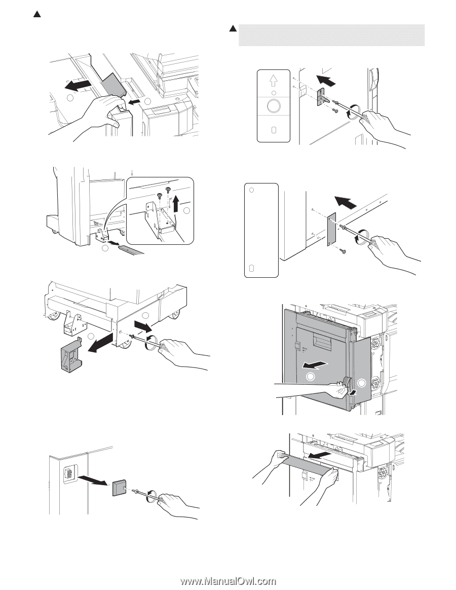
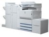
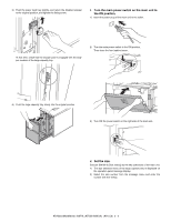
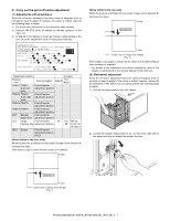
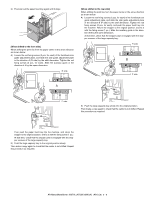
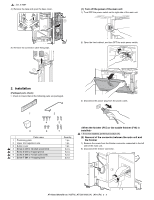
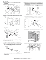
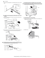
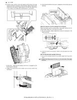
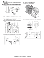
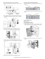
1 : Jan. 9 2004 (3) Removal of the rail, the connectting plate, and the earth plate 1) Separate the finisher and the main unit. 1 2) Attach the positioning pin with two fixing screws I to the left upper section of the main unit. Be careful to the attachment direction of the positioning pin. Note: For fixing screws H and I, use the packaged parts of the ARF15/F16. 2 1 2) Remove two screws which are fixing the connecting plate under the finisher. 3) Attach the earth plate with the fixing screws H (2 pcs.) to the left lower section of the main unit. In this case, attach so that the R mark on the earth plate faces up. 1 R F 2 3) Remove the plate (fixed by one screw) from the rear lower section of the finisher. 1 2 4) Pull out the lock release lever on the left side of the main unit, and open the left door. 4) Go to procedure 5. (4) Attach the positioning pin and the earth plate to the main unit. (Use the packaged parts of the finisher.) 1) Remove the connector cover fixing screw for connection of the finisher joint harness connector, and remove the connector cover. 2 1 5) Remove the paper exit cover on the upper side of the left door. ∗ Only when the finisher and the inserter are installed together, perform this procedure. 6) Close the left door. AR-M550/M620/M700 INSTALLATION MANUAL (AR-CF2) 3 - 3
-
 1
1 -
2
-
3
-
4
-
5
-
6
-
7
-
8
-
9
-
10
-
11
-
12
-
13
-
14
-
15
-
16
-
17
-
18
-
 19
19 -
 20
20 -
 21
21 -
 22
22 -
 23
23 -
 24
24 -
 25
25 -
 26
26 -
 27
27 -
 28
28 -
 29
29 -
30
-
31
-
32
-
33
-
34
-
35
-
36
-
37
-
38
-
39
-
40
-
41
-
42
-
43
-
44
-
45
-
46
-
47
-
48
-
49
-
50
-
51
-
52
-
53
-
54
-
55
-
56
-
57
-
58
-
59
-
60
 |
 |