Sharp AR M550N Installation Manual - Page 35
Note for packing, Installation procedure
 |
View all Sharp AR M550N manuals
Add to My Manuals
Save this manual to your list of manuals |
Page 35 highlights
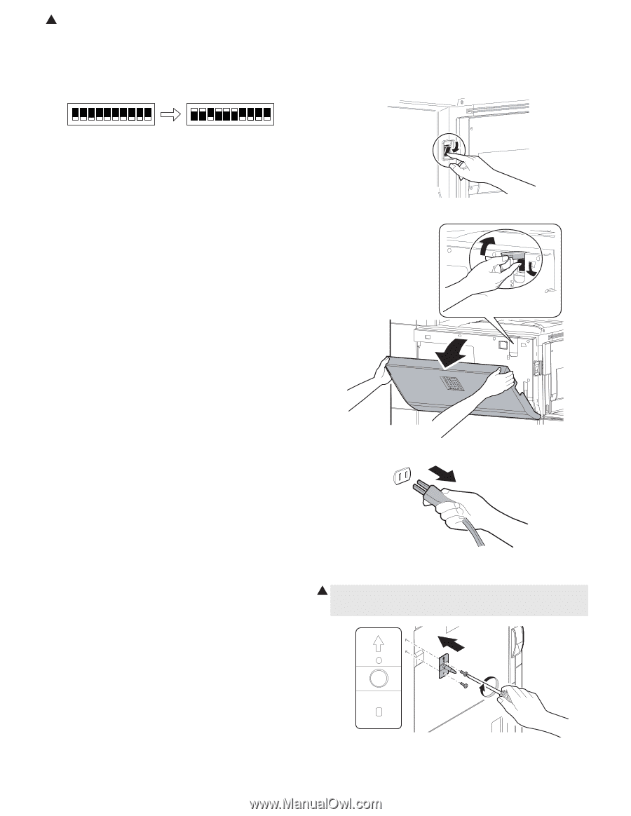
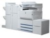
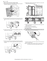
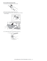
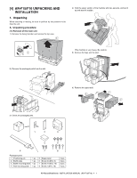
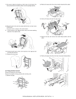
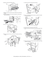
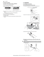
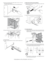
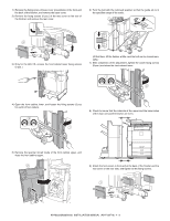
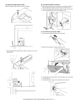
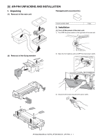
1 : Jan. 9 2004 B. Note for packing (1) Finisher transit fixing member installation 1) Remove the rear cabinet of the finisher. 2) Turn on the power of the main unit. 3) Raise the DIP switch 1, 2, 4, 5, and 6 on the rear of the finisher. 2. Installation A. Installation procedure (1) Turn off the power of the main unit. 1) Turn OFF the power switch on the right side of the main unit. When unpacking Before packing (Shifted to the screw fixing position.) 4) Press SW1 button (left side) of the PWB. (It is located over the DIP switch.) ∗ The finisher tray moves to the screw fixing position. 5) Turn off the power of the main unit. 6) Reset the DIP switch to the original state. 7) Install the cabinet. 8) Install the lift tray rail section fixing members (4 positions) with four screws. 2) Open the front cabinet, and turn OFF the main power switch. 3) Disconnect the power plug from the power outlet. (2) Attach the positioning pin and the earth plate to the main unit. 1 1) Attach the positioning pin with two fixing screws I to the left upper section of the main unit. Be careful to the attachment direction of the positioning pin. AR-M550/M620/M700 INSTALLATION MANUAL (AR-F15/F16) 4 - 4
-
 1
1 -
2
-
3
-
4
-
5
-
6
-
7
-
8
-
9
-
10
-
11
-
12
-
13
-
14
-
15
-
16
-
17
-
18
-
19
-
20
-
21
-
22
-
23
-
24
-
25
-
26
-
27
-
28
-
29
-
 30
30 -
 31
31 -
 32
32 -
 33
33 -
 34
34 -
 35
35 -
 36
36 -
 37
37 -
 38
38 -
 39
39 -
 40
40 -
41
-
42
-
43
-
44
-
45
-
46
-
47
-
48
-
49
-
50
-
51
-
52
-
53
-
54
-
55
-
56
-
57
-
58
-
59
-
60
 |
 |