Sharp AR M550N Installation Manual - Page 23
Installation
 |
View all Sharp AR M550N manuals
Add to My Manuals
Save this manual to your list of manuals |
Page 23 highlights
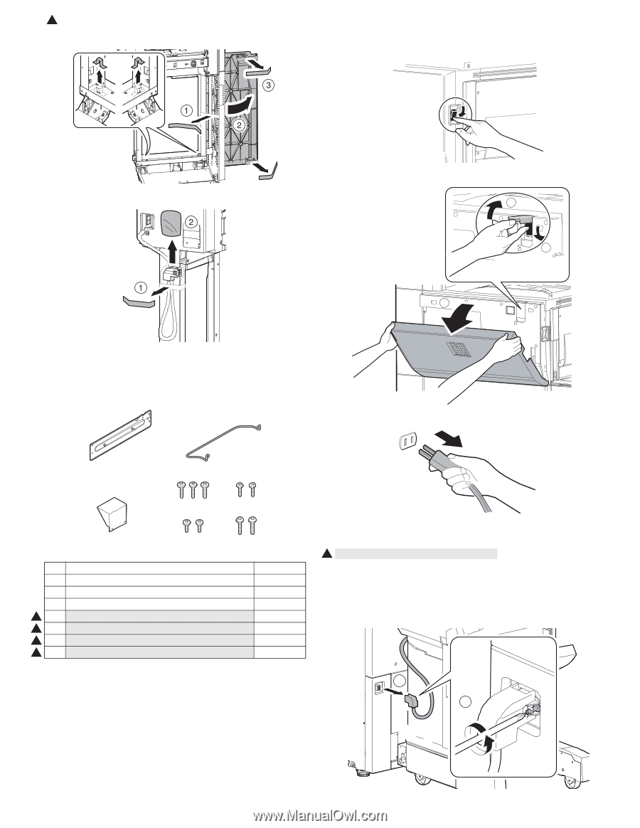
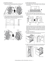
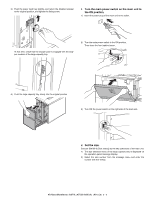
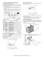
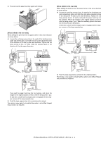
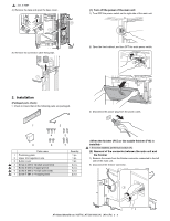
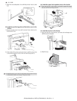
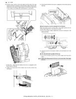
1 : Jan. 9 2004 4) Remove the tape and open the base cover. (1) Turn off the power of the main unit 1) Turn OFF the power switch on the right side of the main unit. 5) Remove the connector cable fixing tape. 2) Open the front cabinet, and turn OFF the main power switch. 2 3 1 2. Installation (Packaged parts check) • Check to insure that all the following parts are packaged. 3) Disconnect the power plug from the power outlet. 1 2 4 3 6 Parts name 1 Positioning plate 2 Upper limit regulation wire 3 Button cover 1 4 Screw C (M4 x 12 small screw bind) 1 5 Screw D (M3 x 8 tapping bind) 1 6 Screw E (M4 x 7 small screw bind) 1 7 Screw F (M4 x 14 tapping bind) 5 7 Quantity 1 pc. 1 pc. 1 pc. 3 pcs. 2 pcs. 2 pcs. 2 pcs. 1 ∗ If it is not installed, perform procedure (4). (2) Removal of the connector between the main unit and the finisher 1) Remove the screw from the finisher connector connected to the left side of the main unit. 2) Disconnect the finisher connector. 2 1 AR-M550/M620/M700 INSTALLATION MANUAL (AR-CF2) 3 - 2
-
 1
1 -
2
-
3
-
4
-
5
-
6
-
7
-
8
-
9
-
10
-
11
-
12
-
13
-
14
-
15
-
16
-
17
-
 18
18 -
 19
19 -
 20
20 -
 21
21 -
 22
22 -
 23
23 -
 24
24 -
 25
25 -
 26
26 -
 27
27 -
 28
28 -
29
-
30
-
31
-
32
-
33
-
34
-
35
-
36
-
37
-
38
-
39
-
40
-
41
-
42
-
43
-
44
-
45
-
46
-
47
-
48
-
49
-
50
-
51
-
52
-
53
-
54
-
55
-
56
-
57
-
58
-
59
-
60
 |
 |