Sharp AR M550N Installation Manual - Page 14
Ar-lc6 Unpacking And, Installation
 |
View all Sharp AR M550N manuals
Add to My Manuals
Save this manual to your list of manuals |
Page 14 highlights
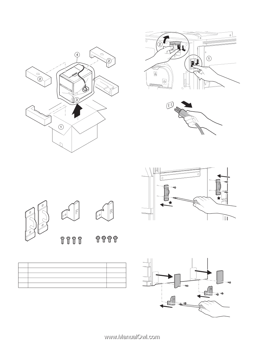
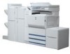
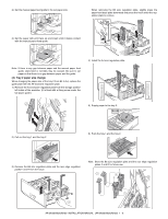
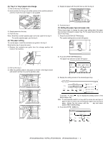
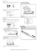
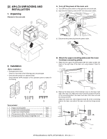
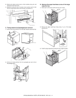
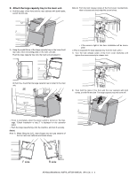
[2] AR-LC6 UNPACKING AND INSTALLATION 1. Unpacking (Removal of the main unit) A. Turn off the power of the main unit. 1) Turn OFF the power switch on the right side of the main unit. 2) Open the front cabinet, and turn OFF the main power switch. 3) Disconnect the power plug from the power outlet. 2. Installation • Packaged parts check Check to insure that all the following parts are packaged. • Check that the printer is in stand-by state. Check that the DATA indicator on the operation panel is neither lit nor blinking. B. Attach the upper mounting plates and the lower front/rear connecting plates. 1) Attach the two upper mounting plates with the rubber portion (5) down to the right side of the main unit using screws A (two for each). 2 3 1 4 5 Parts included 1 Upper mounting plate 2 Lower front connecting plate 3 Lower rear connecting plate 4 Fixing screw A (M4 x 16 small screw bind uniqlo) 5 Fixing screw B (Hex washer S tight M4 x 12) 2pcs. 1pc. 1pc. 4pcs. 4pcs. 2) Remove the fixing screw of the front/rear cover on the lower right side of the main unit. Attach the lower front side (engraved mark F) of the connecting plate to the lower front side of the main unit with two fixing screws B. Attach the lower rear side (engraved mark R) of the connecting plate to the lower rear side of the main unit with two fixing screws B. AR-M550/M620/M700 INSTALLATION MANUAL (AR-LC6) 2 - 1
-
 1
1 -
2
-
3
-
4
-
5
-
6
-
7
-
8
-
 9
9 -
 10
10 -
 11
11 -
 12
12 -
 13
13 -
 14
14 -
 15
15 -
 16
16 -
 17
17 -
 18
18 -
 19
19 -
20
-
21
-
22
-
23
-
24
-
25
-
26
-
27
-
28
-
29
-
30
-
31
-
32
-
33
-
34
-
35
-
36
-
37
-
38
-
39
-
40
-
41
-
42
-
43
-
44
-
45
-
46
-
47
-
48
-
49
-
50
-
51
-
52
-
53
-
54
-
55
-
56
-
57
-
58
-
59
-
60
 |
 |