Sharp AR M550N Installation Manual - Page 43
Ar-p19 Installation
 |
View all Sharp AR M550N manuals
Add to My Manuals
Save this manual to your list of manuals |
Page 43 highlights
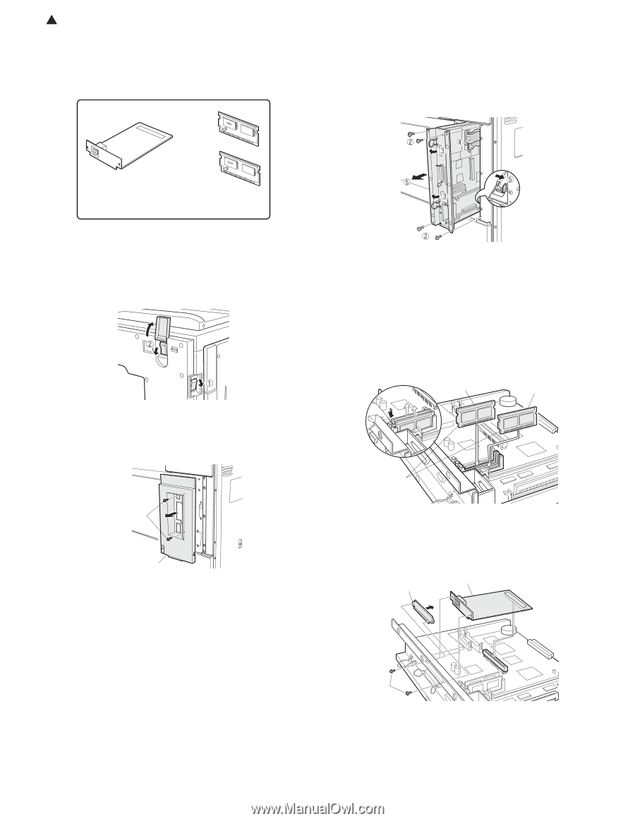
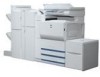
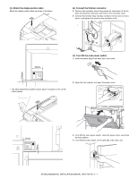
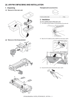
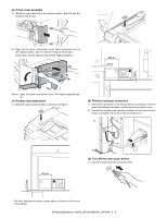
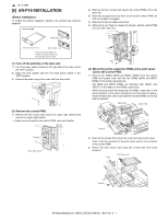
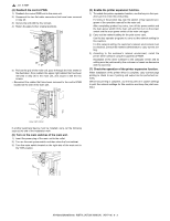
1 : Jan. 9 2004 [6] AR-P19 INSTALLATION To enable the printer expansion function, the product key must be acquired. Parts included MAIN ROM: 1 pc. 2) Remove the four screws that secure the control PWB unit to the main unit. 3) Raise the two grips and hold them to pull out the control PWB unit until the stopper is engaged. 4) Remove the two flat cable connectors. 5) While using your finger to release the stopper, pull the control PWB unit out of the main unit. Print server card: 1 pc. BOOT ROM: 1 pc. ··· Printer utility CD-ROM: 1 pc. Network utility CD-ROM: 1 pc. Product key sheet: 1 sheet (1) Turn off the switches of the main unit. 1) Turn the power switch located on the right side of the main unit to the "OFF" position. 2) Open the front cabinet and turn the main power switch to the "OFF" position. 3) Remove the power plug of the main unit from the outlet. (2) Remove the control PWB. 1) Remove the two screws that secure the upper right cabinet and remove the upper right cabinet. ∗ If cables are connected to the control PWB, remove all cables. Screws Upper right cabinet (3) Mount the printer expansion ROMs and a print server card to the control PWB. 1) Remove the ROMs (MAIN and BOOT ROMs) from the control PWB and replace them with the two ROMs (MAIN and BOOT ROMs) of the printer expansion kit. The MAIN and BOOT ROMs are indicated with "MAIN" and "BOOT" on the labels on the ROMs respectively. When mounting the printer expansion kit ROMs, insert them to the same positions in the same orientations as those before replacement until they click and ensure that the inserted ROMs are locked with the sockets. MAIN ROM BOOT ROM Notches 2) Remove the screws that secure the cover and remove the cover. Then, insert the connector of the print server card to the connector of the control PWB. 3) Secure the print server card using the screws that have been removed. Cover Print server card Screws AR-M550/M620/M700 INSTALLATION MANUAL (AR-P19) 6 - 1
-
 1
1 -
2
-
3
-
4
-
5
-
6
-
7
-
8
-
9
-
10
-
11
-
12
-
13
-
14
-
15
-
16
-
17
-
18
-
19
-
20
-
21
-
22
-
23
-
24
-
25
-
26
-
27
-
28
-
29
-
30
-
31
-
32
-
33
-
34
-
35
-
36
-
37
-
 38
38 -
 39
39 -
 40
40 -
 41
41 -
 42
42 -
 43
43 -
 44
44 -
 45
45 -
 46
46 -
 47
47 -
 48
48 -
49
-
50
-
51
-
52
-
53
-
54
-
55
-
56
-
57
-
58
-
59
-
60
 |
 |