Sharp AR M550N Installation Manual - Page 36
Plate and connection plate installation, Caster adjustment
 |
View all Sharp AR M550N manuals
Add to My Manuals
Save this manual to your list of manuals |
Page 36 highlights
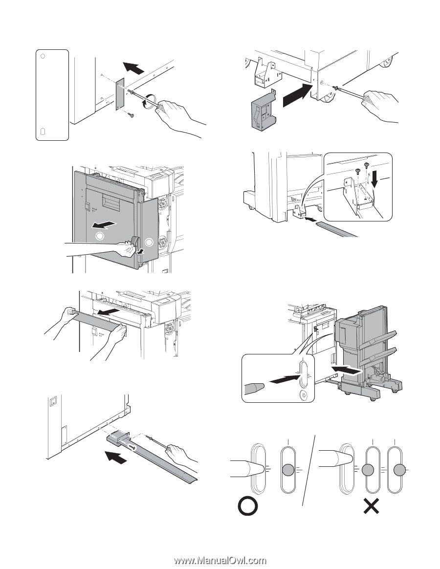
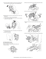
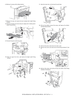
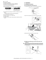
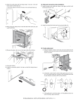
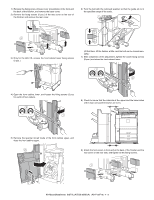
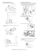
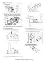
2) Attach the earth plate with the fixing screws H (2 pcs.) to the left lower section of the main unit. In this case, attach so that the R mark on the earth plate faces up. (3) Plate and connection plate installation 1) Install the plate to the finisher as shown in the figure, and fix it with the fixing screw G (1 pc). R F 3) Pull out the lock release lever on the left side of the main unit, and open the left door. 2) Install the rail and the finisher with two screws G (M4 x 6). 2 1 4) Remove the paper exit cover on the upper side of the left door. (4) Caster adjustment A. Bring the finisher closer to the main unit and check that the guide pin of the main unit enters into the connection hole in the finisher smoothly. 5) Close the left door. 6) Install the connection plate to the main unit with the fixing screws I (2 pcs.). B. At that time, check that the center of the guide pin is in the center of the scale marked on the side of the connection hole, and the pin direction coincides with the hole direction. C. If the guide pin is not in the center, or if the guide pin does not enter smoothly, adjust as follows: AR-M550/M620/M700 INSTALLATION MANUAL (AR-F15/F16) 4 - 5
-
 1
1 -
2
-
3
-
4
-
5
-
6
-
7
-
8
-
9
-
10
-
11
-
12
-
13
-
14
-
15
-
16
-
17
-
18
-
19
-
20
-
21
-
22
-
23
-
24
-
25
-
26
-
27
-
28
-
29
-
30
-
 31
31 -
 32
32 -
 33
33 -
 34
34 -
 35
35 -
 36
36 -
 37
37 -
 38
38 -
 39
39 -
 40
40 -
 41
41 -
42
-
43
-
44
-
45
-
46
-
47
-
48
-
49
-
50
-
51
-
52
-
53
-
54
-
55
-
56
-
57
-
58
-
59
-
60
 |
 |