Sharp AR M550N Installation Manual - Page 37
the specified range of the scale.
 |
View all Sharp AR M550N manuals
Add to My Manuals
Save this manual to your list of manuals |
Page 37 highlights
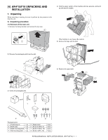
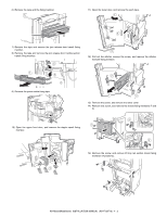
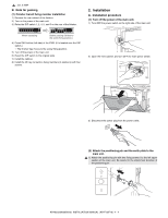
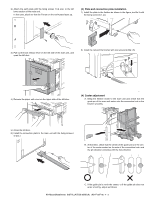
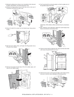
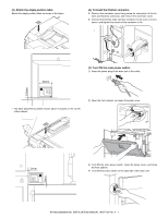
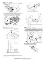
1) Remove the fixing screw of base cover (2 positions) in the front and the back of the finisher, and remove the base cover. 2) Remove the fixing screws (2 pcs.) of the rear cover on the rear of the finisher, and remove the rear cover. 6) Turn the bolt with the removed spanner so that the guide pin is in the specified range of the scale. 3) Only for the AR-F15, remove the front cabinet lower fixing screws (2 pcs.). (At that time, lift the finisher a little, and the bolt can be turned manually.) 7) After completion of the adjustment, tighten the caster fixing screws (8 pcs.) and close the front cabinet lower. 4) Open the front cabinet lower, and loosen the fixing screws (2 pcs for each) of four casters. 8) Check to insure that the intervals at the upper and the lower sides of the main unit and the finisher are even. 5) Remove the spanner stored inside of the front cabinet upper, and close the front cabinet upper. 9) Attach the foot covers in front and at the back of the finisher and the rear cover on the rear side, and tighten all the fixing screws. AR-M550/M620/M700 INSTALLATION MANUAL (AR-F15/F16) 4 - 6
-
 1
1 -
2
-
3
-
4
-
5
-
6
-
7
-
8
-
9
-
10
-
11
-
12
-
13
-
14
-
15
-
16
-
17
-
18
-
19
-
20
-
21
-
22
-
23
-
24
-
25
-
26
-
27
-
28
-
29
-
30
-
31
-
 32
32 -
 33
33 -
 34
34 -
 35
35 -
 36
36 -
 37
37 -
 38
38 -
 39
39 -
 40
40 -
 41
41 -
 42
42 -
43
-
44
-
45
-
46
-
47
-
48
-
49
-
50
-
51
-
52
-
53
-
54
-
55
-
56
-
57
-
58
-
59
-
60
 |
 |