TP-Link TL-WA7210N User Guide - Page 14
Conventions, Panel Layout - bridge mode
 |
View all TP-Link TL-WA7210N manuals
Add to My Manuals
Save this manual to your list of manuals |
Page 14 highlights
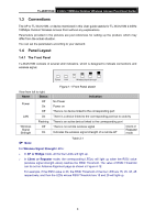
TL-WA7210N 2.4GHz 150Mbps Outdoor Wireless Access Point User Guide 1.3 Conventions The AP or TL-WA7210N, or device mentioned in this User guide stands for TL-WA7210N 2.4GHz 150Mbps Outdoor Wireless Access Point without any explanations. Parameters provided in the pictures are just references for setting up the product, which may differ from the actual situation. You can set the parameters according to your demand. 1.4 Panel Layout 1.4.1 The Front Panel TL-WA7210N consists of several LED indicators, which is designed to indicate connections and wireless signal. Figure 1-1 Front Panel sketch View from left to right. Name Status Off Power On Off Indication No Power Power on There is no device linked to the corresponding port LAN On There is a device linked to the corresponding port but no activity Wireless Signal Strength Flashing Off On There is an active device linked to the corresponding port There is no remote wireless signal Indicates the wireless signal strength of a remote AP Client or Repeater mode Note: Table 2-1 For Wireless Signal Strength LEDs: In AP or Bridge mode, all the four LEDs will light up. In Client or Repeater mode, the corresponding LED(s) will light up when the RSSI value (wireless signal strength value) reaches the RSSI Threshold. The value of RSSI Threshold can be set on Antenna Alignment page as shown in Figure 4-12. For example, if the RSSI value is 30, the RSSI Threshold of the four LED are 15, 25, 35, 45 respectively, and then the LEDs whose RSSI Threshold are 15 and 25 will light up. 4
-
 1
1 -
2
-
3
-
4
-
5
-
6
-
7
-
8
-
 9
9 -
 10
10 -
 11
11 -
 12
12 -
 13
13 -
 14
14 -
 15
15 -
 16
16 -
 17
17 -
 18
18 -
 19
19 -
20
-
21
-
22
-
23
-
24
-
25
-
26
-
27
-
28
-
29
-
30
-
31
-
32
-
33
-
34
-
35
-
36
-
37
-
38
-
39
-
40
-
41
-
42
-
43
-
44
-
45
-
46
-
47
-
48
-
49
-
50
-
51
-
52
-
53
-
54
-
55
-
56
-
57
-
58
-
59
-
60
-
61
-
62
-
63
-
64
-
65
-
66
-
67
-
68
-
69
-
70
-
71
-
72
-
73
-
74
-
75
-
76
-
77
-
78
-
79
-
80
-
81
-
82
-
83
-
84
-
85
-
86
-
87
-
88
-
89
-
90
-
91
-
92
-
93
-
94
-
95
-
96
-
97
-
98
-
99
-
100
-
101
-
102
-
103
-
104
-
105
-
106
-
107
-
108
-
109
-
110
-
111
-
112
-
113
-
114
-
115
-
116
-
117
-
118
-
119
-
120
-
121
-
122
-
123
-
124
-
125
-
126
-
127
-
128
-
129
-
130
-
131
-
132
-
133
-
134
-
135
-
136
-
137
-
138
-
139
-
140
-
141
-
142
-
143
-
144
-
145
-
146
-
147
-
148
-
149
-
150
 |
 |
