Toshiba Portege M400 PPM40C-TD30TEF Users Manual Canada; English - Page 190
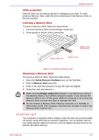
Screw in the two screws and replace the memory module cover.
 |
View all Toshiba Portege M400 PPM40C-TD30TEF manuals
Add to My Manuals
Save this manual to your list of manuals |
Page 190 highlights
Optional Devices 10. Fit the memory module's connectors into the socket at about a 45 degree angle and push the module down until latches on either side snap into place. Align the notch of the memory module with that of the memory slot and gently insert the module into the slot. Slot B Slot A Figure 8-10 Installing the memory module 11. Screw in the two screws and replace the memory module cover. Screws Memory module cover Figure 8-11 Seating the memory module cover 12. Tuck the keyboard ribbon cable into the groove under the palm rest. 8-12 Keyboard ribbon cable Figure 8-12 Tuck the keyboard ribbon cable User's Manual
-
 1
1 -
2
-
3
-
4
-
5
-
6
-
7
-
8
-
9
-
10
-
11
-
12
-
13
-
14
-
15
-
16
-
17
-
18
-
19
-
20
-
21
-
22
-
23
-
24
-
25
-
26
-
27
-
28
-
29
-
30
-
31
-
32
-
33
-
34
-
35
-
36
-
37
-
38
-
39
-
40
-
41
-
42
-
43
-
44
-
45
-
46
-
47
-
48
-
49
-
50
-
51
-
52
-
53
-
54
-
55
-
56
-
57
-
58
-
59
-
60
-
61
-
62
-
63
-
64
-
65
-
66
-
67
-
68
-
69
-
70
-
71
-
72
-
73
-
74
-
75
-
76
-
77
-
78
-
79
-
80
-
81
-
82
-
83
-
84
-
85
-
86
-
87
-
88
-
89
-
90
-
91
-
92
-
93
-
94
-
95
-
96
-
97
-
98
-
99
-
100
-
101
-
102
-
103
-
104
-
105
-
106
-
107
-
108
-
109
-
110
-
111
-
112
-
113
-
114
-
115
-
116
-
117
-
118
-
119
-
120
-
121
-
122
-
123
-
124
-
125
-
126
-
127
-
128
-
129
-
130
-
131
-
132
-
133
-
134
-
135
-
136
-
137
-
138
-
139
-
140
-
141
-
142
-
143
-
144
-
145
-
146
-
147
-
148
-
149
-
150
-
151
-
152
-
153
-
154
-
155
-
156
-
157
-
158
-
159
-
160
-
161
-
162
-
163
-
164
-
165
-
166
-
167
-
168
-
169
-
170
-
171
-
172
-
173
-
174
-
175
-
176
-
177
-
178
-
179
-
180
-
181
-
182
-
183
-
184
-
 185
185 -
 186
186 -
 187
187 -
 188
188 -
 189
189 -
 190
190 -
 191
191 -
 192
192 -
 193
193 -
 194
194 -
 195
195 -
196
-
197
-
198
-
199
-
200
-
201
-
202
-
203
-
204
-
205
-
206
-
207
-
208
-
209
-
210
-
211
-
212
-
213
-
214
-
215
-
216
-
217
-
218
-
219
-
220
-
221
-
222
-
223
-
224
-
225
-
226
-
227
-
228
-
229
-
230
-
231
-
232
-
233
-
234
-
235
-
236
-
237
-
238
-
239
-
240
-
241
-
242
-
243
-
244
-
245
-
246
-
247
-
248
-
249
-
250
-
251
-
252
-
253
-
254
-
255
-
256
-
257
-
258
-
259
-
260
-
261
-
262
-
263
-
264
-
265
-
266
-
267
-
268
-
269
-
270
-
271
-
272
-
273
-
274
-
275
-
276
-
277
-
278
-
279
-
280
-
281
-
282
-
283
-
284
-
285
-
286
-
287
-
288
-
289
-
290
-
291
-
292
-
293
-
294
-
295
-
296
-
297
-
298
-
299
-
300
-
301
-
302
-
303
-
304
-
305
-
306
 |
 |
8-12
User’s Manual
Optional Devices
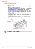
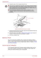
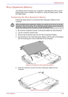
10. Fit the memory module's connectors into the socket at about a 45
degree angle and push the module down until latches on either side
snap into place.
Align the notch of the memory module with that of the memory slot and
gently insert the module into the slot.
Figure 8-10 Installing the memory module
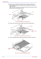
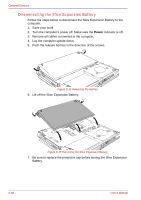
11. Screw in the two screws and replace the memory module cover.
Figure 8-11 Seating the memory module cover
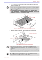
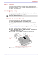
12. Tuck the keyboard ribbon cable into the groove under the palm rest.
Figure 8-12 Tuck the keyboard ribbon cable
Slot B
Slot A
Screws
Memory module
cover
Keyboard ribbon
cable