Vtech CM18445 User Manual - Page 4
System Overview - handset
 |
View all Vtech CM18445 manuals
Add to My Manuals
Save this manual to your list of manuals |
Page 4 highlights
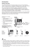
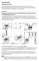
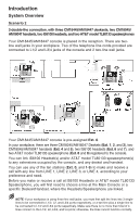
Introduction System Overview The following pages illustrate two possible scenarios of how your 4-line telephone system can be setup in your workplace. The actual setup depends on the environment and settings in your workplace. Scenario 1 4-single-line connection, with four CM18245/AM18247 desksets and five CM18045/AM18047 handsets Your CM18445/AM18447 console is placed in the reception. There are only single-line wall jacks in your workplace. The 4 single-line cords (model RJ11; purchased separately) are connected to L1, L2, L3, and L4 jacks of the console and 4 single-line wall jacks. Your CM18445/AM18447 console is pre-assigned Ext. 0. In your workplace, there are four CM18245/AM18247 deskets (Ext. 1, 2, 3, and 4) and five CM18045/AM18047 handsets (Ext. 5, 6, 7, 8, and 9) registered to the console. You can use any of the ten stations (Ext. 0, and 1-9) to make and receive a call with any line from LINE 1, LINE 2, LINE 3, or LINE 4, according to your preference and need. NOTE: If your workplace is using two-line wall jacks, please refer to Scenario 2. For three-line wall jacks, you must first split the lines into 3 single-lines to be connected to L1/2, L2, and L3/4 ports respectively, or a two-line plus a single line to be connected to L1/2 and L3/4 ports respectively.
-
 1
1 -
 2
2 -
 3
3 -
 4
4 -
 5
5 -
 6
6 -
 7
7 -
 8
8 -
 9
9 -
 10
10 -
11
-
12
-
13
-
14
-
15
-
16
-
17
-
18
-
19
-
20
-
21
-
22
-
23
-
24
-
25
-
26
-
27
-
28
-
29
-
30
-
31
-
32
-
33
-
34
-
35
-
36
-
37
-
38
-
39
-
40
-
41
-
42
-
43
-
44
-
45
-
46
-
47
-
48
-
49
-
50
-
51
-
52
-
53
-
54
-
55
-
56
-
57
-
58
-
59
-
60
-
61
-
62
-
63
-
64
-
65
-
66
-
67
-
68
-
69
-
70
-
71
-
72
-
73
-
74
-
75
-
76
-
77
-
78
-
79
-
80
-
81
-
82
-
83
-
84
-
85
-
86
-
87
-
88
-
89
-
90
-
91
-
92
-
93
-
94
-
95
-
96
-
97
-
98
-
99
-
100
-
101
-
102
-
103
-
104
-
105
-
106
-
107
-
108
-
109
-
110
-
111
-
112
-
113
-
114
-
115
-
116
-
117
-
118
-
119
-
120
-
121
-
122
 |
 |
